
The connecting rods must match the cylinder number. The designations on the connecting rod and the connecting rod cap must be located one below the other. The arrows on the piston heads must point towards the front of the engine.
Piston ring locks must be evenly spaced around the piston circumference at an angle of 120°.
Put a mandrel on the piston and compress the piston rings in the grooves (see fig. 71).
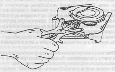
Pic. 71. Installation of a piston with a mandrel for compressing piston rings.
Put short pieces of rubber or plastic hose on the connecting rod cap bolts to prevent damage to the cylinder mirror.
Turn the crankshaft to the BDC position of the two connecting rod journals.
Insert the connecting rod assembly into the cylinder, while laying the cylinder block on its side so that the connecting rod is directed by the lower head to the crankshaft journal and cannot damage the cylinder mirror. The upper connecting rod bearing must already be installed in the connecting rod head.
Insert the piston into the cylinder and, using a mandrel, advance along the cylinder until the liner fits on the connecting rod journal of the crankshaft.
Insert the second connecting rod bearing into the connecting rod cover, lubricate with engine oil, put the cover on the mounting bolts, before that, remove the hose sections and press the cover against the connecting rod. Finally check the location of all symbols on the piston, connecting rod and connecting rod cap.
Lubricate the bearing surfaces under the mounting nuts on the connecting rod cap.
After installing the connecting rod on the crankshaft, the latter must be rotated several times to self-adjust the connecting rod.
Once again check the location of all marks on the parts.
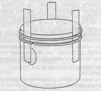
Pic. 72. Connecting rod assembly.
1 - connecting rod and connecting rod cap,
2 - hole for oil supply,
3 - grooves for fastening the liners.
Using a feeler gauge, determine the axial clearance between the bottom head of the connecting rod and the connecting rod journal of the crankshaft.