
Valve springs
All instructions for an eight-cylinder engine apply equally to a six-cylinder engine.
Valve guides
Clean the guide bushings by pulling a rag soaked in gasoline through the hole. Clean the outer parts of the guide bushings with a wire brush clamped in the chuck of an electric drill.
Check the wear of the valve guides with a gauge. If the non-going side of the gauge fits into the guide bore, the valve guide must be replaced.
The valve guide is pressed out with a mandrel. It is possible to install a valve guide of nominal size 1, which is pressed into the cylinder head with a mandrel until the adjusting ring stops against the end surface of the head. It is possible to install an oversized valve guide, the hole is then machined with a manual reamer. Before installation, it is recommended to cool the new guide bush in dry ice, it is advisable to have this operation carried out by a specialist workshop.
Check the general condition of the cylinder head before replacing the valve guide. After the valve guide is pressed in, the hole must be reamed to 9.000...9.015 mm for intake valves or 11.00...11.018 mm for exhaust valves. The intake valve guide is longer.
When replacing a valve guide, a new valve must be installed and the valve seat must be remachined.
After replacing the valve guide, the valve seat must be countersinked. If machining of the valve seat is no longer possible, do not change the valve guide.
Valve seats
If the camshaft bearings are worn, oversized bushings can be installed (camshaft journals are ground) or installing a new cylinder head.
Check for wear or damage to valve seat surfaces. Minor wear is eliminated by countersinking at an angle of 45°. If this repair is no longer possible, the valve seat must be replaced.
The valve seats are pressed into the cylinder head and, to remove the old rings, they are drilled out with a special tool, preventing damage to the cylinder head. Then check the size of the hole "D1" (pic. 62) and, if necessary, processed to the next repair size. The valve seat of the repair size should provide an interference fit of 0.074... 0.1 mm.
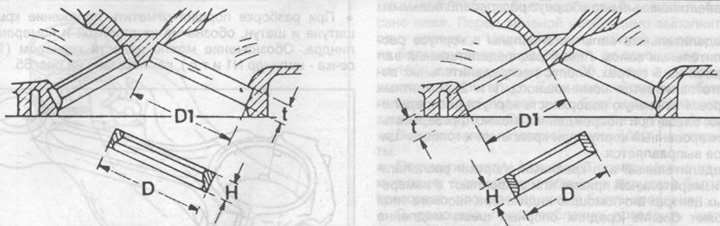
Pic. 62. Measurement of the bore for the intake and exhaust valve seats in the cylinder head. On the left under the inlet, on the right under the exhaust valves.
Heat the cylinder head in a water bath to 90°C, and cool the valve seat with dry ice, then press the valve seat into the cylinder head using a mandrel.
Machine the valve seat with a drill or grinder. Install the valve and determine the size "A", shown in fig. 63. Reducing the size "A" possible after machining the mating plane of the cylinder head.
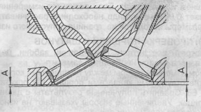
Pic. 63. The minimum distance between the valve disc and the split surface of the cylinder head.
After machining, measure the width of the chamfer of the valve seat. If the size of the chamfer of the inlet valve seat does not correspond to the dimensions in the tables, it is necessary to bring it to the required values by countersinking from above with a countersink at an angle of 15°and from below by a countersink at an angle of 60°.
Then it is necessary to grind the working chamfers of the valve seat and the valve using lapping paste. Apply the paste on the working chamfer of the valve seat and install the valve, use the suction cup to rotate the valve in two directions, pressing it against the surface of the seat.
After lapping, clean the parts of dirt and lapping paste residues and check the working chamfers of the valve seat and valve. On both parts, a continuous opaque ring should be clearly visible, corresponding to the width of the working chamfer of the valve seat. Use a lead rod to put a strip on the working chamfer of the valve, then carefully insert the valve into the guide sleeve and, pressing against the valve seat, turn the valve 90°.
Remove the valve from the guide sleeve and check the working chamfer of the valve seat, if the traces of the lead rod are evenly distributed over the entire surface of the working chamfer, this means that the grinding is done correctly and the cylinder head is suitable for further operation. If there are gaps, repeat the lapping or use a new cylinder head.
Valve
All of the information on eight-cylinder engine valves given above applies equally to six-cylinder engines. A designation is applied to the end of the valve stem and valves with the same designation can be installed.
Check the valves for compliance with the data given in the tables of sizes and adjustment data, and replace all valves that do not comply with these data.
When replacing exhaust valves, pay attention to safety precautions when disposing of the valves.
Always state year of manufacture and engine number when ordering.
Cylinder head
The instructions given for eight-cylinder engines also apply to six-cylinder engines. The mating planes of the cylinder head can be milled with subsequent size adjustment "A" (see fig. 63) to the required value.
Camshaft and camshaft housing
The camshafts are installed in the camshaft housing. The left camshaft rotates on 5 bearings. The camshaft housing is manufactured in nominal, 1 and 2 repair sizes. The split surface of the camshaft housing can be milled in case of damage. The deformed housing is straightened when attached to the cylinder head.
The camshaft is placed with extreme supports on a measuring prism or fixed in measuring centers and, using a dial indicator, check the runout of the middle bearing journals by slowly rotating the camshaft. If the runout exceeds 0.01 mm, then the shaft is rejected and must be replaced.
Cylinder head assembly
The cylinder head is assembled in the reverse order of disassembly. Install valves only in accordance with the designations on the cardboard tags. Oil seals should only be installed using a special mandrel and their size must correspond to the diameter of the valve stem.
Installation of camshafts and camshaft housings are described in the relevant sections.