
Put the hood of the car in a vertical position as when removing the engine.
Disconnect the wires from the battery.
Drain the coolant from the cooling system (section 5.1).
Remove air filter.
In vehicles with adjustable wheel suspension, unscrew the four bolts securing the suspension hydraulic pump, remove the pump together with the hoses and set aside. Remove pump drive parts.
On vehicles with air conditioning, remove the compressor and move it to one side along with the pipe.
Remove the two covers on the front side of the camshaft housing.
Remove all parts, pipes, wires of the cooling system, power system, electrical equipment, etc. from the cylinder head and intake manifold.
Disconnect the fuel control links.
Disconnect oil line from cylinder head.
Disconnect the oil level indicator tube in the automatic transmission and set aside.
Remove the hose connecting the thermostat housing and the coolant pump and the bypass hose from the pump.
Disconnect the exhaust pipe from the manifold on the engine and disconnect the pipe mounting on the gearbox. On vehicles with a carburetor, remove the heater housing.
Remove the rocker arms as described below.
Turn the engine crankshaft to TDC in the 1st cylinder and put marks on the camshaft sprockets and the drive chain, these marks must be aligned during assembly. To rotate the crankshaft, use a size 27 socket wrench with a ratchet, which must be put on the center pulley mounting bolt. The rotation of the chain drive by the bolts of the camshaft sprockets is not allowed. Always turn the crankshaft in the direction of rotation (clockwise).
Unscrew shown in fig. 56 a plug that blocks access to the chain tensioner. Remove spring and O-ring.
Pic. 56. Removing the chain tensioner
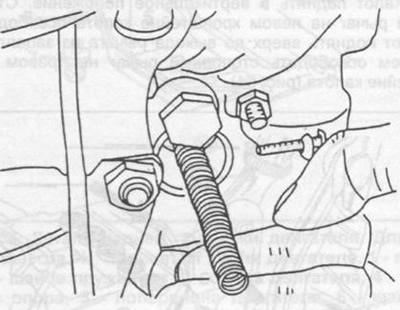
Loosen the camshaft sprocket mounting bolt while holding the shaft from turning with a wrench of the appropriate size, installed on the cam in the middle of the shaft, as shown in Fig. 57.
Pic. 57. Fixing the camshaft when loosening or tightening the sprocket mounting bolt.
Remove the chain guide from the camshaft housing (see relevant recommendations below).
Move the camshaft back and remove the sprocket.
To turn away bolts of fastening of a head of cylinders in return sequence, shown on fig. 58. To unscrew, use a socket wrench with an extension and a handle that provides the necessary force.
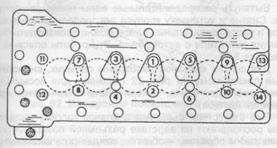
Pic. 58. Order of an inhaling of bolts of fastening of a head of cylinders.
Unscrew the M8 bolts with a 6 mm hexagon. Use an extension to unscrew. Use a magnet to remove the bolts.
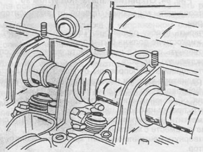
Pull the drive chain up and press the chain tensioner shoe to the engine axle.
Remove cylinder head. To make work easier, the head can be hung on the lifting eye by the lifting eyes.
Thoroughly clean the mating surfaces of the cylinder head and block.
If necessary, repair the cylinder head as described in section 3.3.2. When installing the cylinder head, install a new gasket following the instructions below.
When installing the cylinder head, observe the following instructions:
Place a new gasket on the two dowel pins.
Put two wooden slats 15x35x240 in size on the gasket. In the front side, put the rail on the narrow side, in the back on the wide side.
Hang the cylinder head on the lifting eyes on the load handler. In the absence of a lifting device, the installation of the cylinder head is correspondingly more complicated.
Lay the cylinder head on the rails and insert the drive chain and tensioner shoe into the opening of the cylinder head.
Lift the front side of the cylinder head, remove the rail towards the exhaust manifold and lower the head into the dowel pin.
Raise the rear side of the cylinder head, remove the rail towards the exhaust manifold and lower the head onto the dowel pin.
Lubricate the cylinder head bolts with engine oil.
Screw in the fastening bolts and tighten with a preliminary torque of 40 Nm in the sequence shown in fig. 58.
New bolts are tightened in the same sequence, but with a torque of 90 Nm. Pause for 10 minutes.
Fit three hexagon socket screws and tighten to 25 Nm.
Final tighten the cylinder head bolts in the same sequence to 90 Nm.
Check the ease of rotation of the camshafts.
Put the upper sprocket on the chain, lubricate the sprocket axle, insert the axle into the sprocket and use a hammer to press the axle into the cylinder head until it stops.
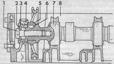
Put the sprocket together with the distance ring on the intake camshaft. Lubricate the support sleeve and insert into the bearing. On fig. 59 shows a sectional view of the intake camshaft with the above details.
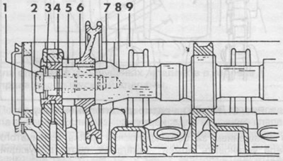
Pic. 59. Section of the intake camshaft.
1 - fastening bolt,
2 - disc washers,
3 - support sleeve,
4 - bearing,
5 - remote ring,
6 - camshaft sprocket,
7 - key,
8 - camshaft,
9 - camshaft housing.
Put the sprocket with the drive chain on the exhaust camshaft. Lubricate the support sleeve and insert into the bearing. On fig. 60 is a sectional view of the exhaust camshaft with the above details.
Pic. 60. Section of the exhaust camshaft.
1 - fastening bolt,
2 - disc washer,
3 - support sleeve,
4 - bearing,
5 - camshaft sprocket,
6 - key,
7 - camshaft,
8 - camshaft housing.
Screw in the sprocket mounting bolts together with the washers, but do not tighten.
Check the alignment of the marks on the camshaft sprockets and the drive chain.
Turn the crankshaft to the TDC of the piston of the first cylinder, check the alignment of the marks on the camshafts and their housing, as shown in fig. 61, on the outer surface of the damper, the designation "00" should be located under the TDC indicator pin.
Install the chain guide into the camshaft housing, being careful not to let the chain come off the sprocket teeth.
Screw on the chain tensioner and tighten the plug by hand.
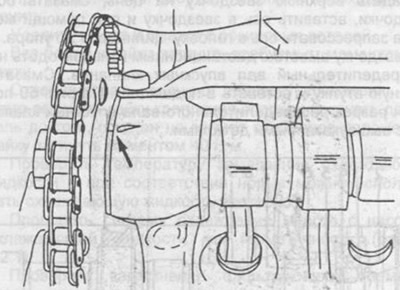
Pic. 61. Marks on the camshaft and housing.
By turning the bolt of the crankshaft pulley, set the ignition moment corresponding to the designation "00".
After repairing the cylinder head or camshaft housing, check the valve timing.
Tighten the camshaft sprocket bolts to 80 Nm, holding the camshafts from turning as described above. Install the variable wheel suspension hydraulic pump drive parts and the pump.
Install the valve rockers.
Attach the chain tensioner. The required tension of the drive chain is provided by the combined action of the tensioner spring and the oil pressure in the lubrication system. The pressure relief valve and check valve maintain a constant pressure in the chain tensioner during operation, independent of the pressure in the lubrication system.
Adjust valve clearances (section 3.12).
Perform all other work in reverse order. For vehicles operated in Switzerland, additionally adjust the composition of the exhaust gases.
Adjust the tension of the drive belts of the units (section 4.3.2).
Adjustment of clearances in the valve mechanism or additional tightening of the cylinder head bolts on a warm engine is not required.