
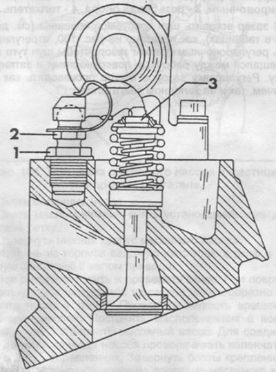
Pic. 98. Valve clearance (M116/117 engine).
1 - threaded support,
2 - adjusting bolt,
3 - pusher.
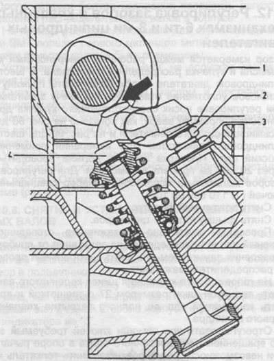
Pic. 99. Measuring the clearance in the valve mechanism, the place of measurement is indicated by an arrow (M110 engine).
1 - spring (remove before measurement),
2 - adjusting bolt,
3 - threaded support,
4 - pusher.
Remove air filter.
Remove cylinder head cover.
Check if the ignition is off, disconnect the green wire of the ignition distributor from the ignition control device or remove the center wire from the ignition distributor.
Put a socket wrench size 27 with a ratchet on the head of the crankshaft pulley bolt and rotate the crankshaft until the valves of the first cylinder are completely closed.
Adjust the required clearance with wrenches by turning the adjusting bolt in the lever support. If adjustment is not possible, replace the pusher on the spring plate. Pushers are available in various heights.
Insert a feeler gauge of the required thickness into the gap (see data in tables), as shown in fig. 100, adjust the gap with the adjusting bolt so that the probe moves tightly between the working surfaces and tighten the nut. Adjustment of backlashes can be made both on hot, and on cold engines.
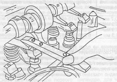
Pic. 100. Checking the clearance in the valve mechanism with a flat probe. The toe of the cam must be pointing up.
Turn the crankshaft half a turn and adjust the clearance in the valve mechanisms of cylinder 3.
Turn the crankshaft half a turn and adjust the clearance in the valve mechanisms of 4 cylinders.
Turn the crankshaft half a turn and adjust the clearance in the valve mechanisms of 2 cylinders.
Perform the rest of the work in reverse order.