
On vehicles with adjustable wheel suspension, unscrew the suspension hydraulic pump mounting bolts and remove the pump together with the pipelines.
On vehicles with air conditioning, remove the air conditioning compressor and set aside.
Drain the coolant from the cooling system, remove the upper hose between the engine and the radiator.
Loosen the fastening of the right cover on the front side of the camshaft housing, as shown in fig. 92.
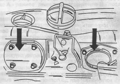
Pic. 92. The arrows show the position of the covers on the camshaft housing. The right cover must be removed.
Remove the rocker arms as described in previous section.
Hold the right camshaft in the middle with a torque wrench and unscrew the sprocket mounting bolt. Rotate the crankshaft to TDC on the number one cylinder. Turn the shaft with a socket wrench size 27, dressed on the central bolt of the crankshaft pulley. Rotate the shaft only in the direction of travel.
Remove chain tensioner and springs (see fig. 93).
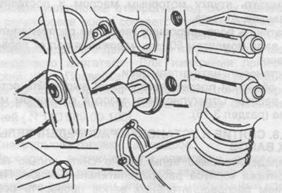
Pic. 93. Removing the drive chain tensioner.
Remove the chain guide from the camshaft housing (section 3.10.4).
Pull the right camshaft back and remove the camshaft sprocket, then return the shaft to its original position.
In the reverse order shown in fig. 94 Loosen the M8 bolts. The five bolts on the rear side and the two M8 bolts, indicated by the arrows, do not loosen, they secure the cylinder head to the cylinder block.
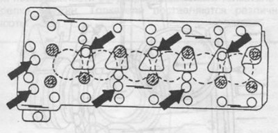
Pic. 94. The order of tightening the bolts of the camshaft housing. When removing the housing, unscrew the bolts in reverse order.
Remove the camshaft housing together with the shafts.
When installing the camshaft housing, carry out the following work:
Thoroughly clean the mating surfaces of the cylinders and camshaft housings and install a new gasket (metal foil). Carefully install camshaft housing.
Lubricate the threads and bearing surfaces of the mounting bolts with engine oil and tighten the bolts.
Tighten the cylinder head bolts in sequence:
- Hex socket bolts with double edge in the head of the bolt: all bolts in the sequence shown in fig. 94 tighten to 110 Nm, then turn bolt heads 2, 3, 5, 8, 10, 11, 12, 13 and 14 another 90° (quarter turn). Tighten bolts 1,4, 6, 7 and 9 below to 110 Nm.
- Bolts with an internal hexagon in the bolt head: all bolts in accordance with the diagram in fig. 58 tighten to 70 Nm. When re-tightening, the torque should be 90 Nm, while the bolts 1.4, 6, 7 and 9 must first be loosened and tightened again.
- Tighten M8 bolts to 25 Nm. Bolt M8, located next to bolt 12, can only be tightened with the camshaft sprocket removed. After tightening the mounting bolts, check the ease of rotation of the camshafts in the housing.
Put an asterisk on the right camshaft, at TDC of the piston of the first cylinder, the marks on the sprocket and the drive chain must be aligned.
Install the chain guide, making sure the chain does not come off the sprockets.
Lubricate the bushing with engine oil and place in the housing bearing.
Tighten the camshaft sprocket bolt to 80 Nm while holding the camshaft from turning.
Install the chain tensioner.
Perform the rest of the work in reverse order. Adjust valve clearance (section 3.13).