
Remove the two rocker arms of the first cylinder by turning the crankshaft until the toes of the corresponding cams point upwards.
Replace the tappets on the valves of the first cylinder with special measuring tappets and install the valve levers without springs. Using the adjusting bolts in the valve lever supports, select the gap between the working surfaces of the cam and the valve lever.
Mount and secure tool 110 589 102 100 (see fig. 96).
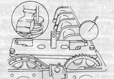
Pic. 96. A device for checking the valve timing.
Inlet valve: with the valve closed, place a dial indicator in the tool and in this position fix the indicator in the tool. Rotate the indicator scale to "0" against the big arrow. Slowly turn the crankshaft until the indicator reads 2... 1 mm and read the readings on the damper under the pointer pin. They must match the data in the table "Intake valve opening after TDC".
Exhaust valve: install and fasten the indicator on the exhaust valve as described above. Rotate the crankshaft slowly until the exhaust valve is fully open and then note the reading as the valve closes "1 mm" small arrow and "ABOUT" big. This corresponds to 2 mm valve travel before closing.