
Cars BMW Cars Volkswagen Cars Chevrolet Cars Land Rover Cars Lada Cars Honda Cars Peugeot
English Русский
Български
Беларускі
Український
Српски
Hrvatski
Română
Polski
Slovenský
Magyar
Bookmark News and articles Sitemap Feedback Site search
MercedesMan.ru


A-Class C-Class E-Class G-Class M-Class S-Class Others
W123 (1976-1985) W124 (1984-1995) W210 (1996-2002)
  • Main
  • E-Class
  • W210 (1996-2002)
  • Gasoline engines
  • Control system
  • Removal and installation ignition coils

Removal and installation ignition coils (Mercedes-Benz E-Class W210)

0
Contents: 4- and 6-cylinder in-line engines ↡ V6 Engine ↡ V8 Engine ↡
The ignition system of gasoline engines does not have moving, wearing parts, so its service life and reliability are significant. To improve the starting qualities of the engine, the ignition spark on a cold engine is generated several times during the working cycle. The memory of the electronic unit contains an ignition characteristic, according to which the optimal ignition advance angle is determined. On a 4-cylinder engine there is one, and on an 8-cylinder engine - two detonation sensors. When detonation combustion begins, the control unit sends a signal to change the ignition advance angle towards "retardation". As a result of the operation of engines without detonation combustion, the service life of the parts increases significantly.

4- and 6-cylinder in-line engines


Removal


1. Turn off the ignition.

2. Remove the air filter cross pipe.
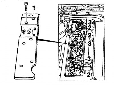
Fig. 5.38. Removing the spark plug cover: 1 – lid; 2, 3 – pin connector

Fig. 5.38. Removing the spark plug cover: 1 – lid; 2, 3 – pin connector


3. Remove cover 1 (Fig. 5.38) of the spark plugs.

Note: The drawing is for a 6-cylinder in-line engine.


4. Disconnect the contact connectors from the ignition coils 3.

Fig. 5.39. Ignition coil: 1, 3 – connectors; 2 – guide pin; 4 – ignition coil

Fig. 5.39. Ignition coil: 1, 3 – connectors; 2 – guide pin; 4 – ignition coil


5. Disconnect the 2 high voltage wire connectors.

Note: In Fig. 5.39, connector 3 of ignition coil 4 is connected to the spark plug. Connector 1 is connected to the spark plug via a high-tension wire. Guide pin 2 connects the ignition coil to ground.
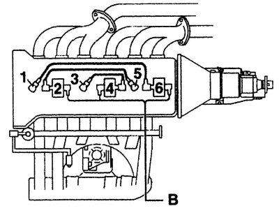

Fig. 5.40. Wiring diagram of ignition coils of a 6-cylinder in-line engine. The numbers indicate…

Fig. 5.40. Wiring diagram of ignition coils of a 6-cylinder in-line engine. The numbers indicate the tips of spark plugs from cylinders 1 to 6; B - wires


Fig. 5.40 shows the connection diagram of the ignition coils with spark plugs for a 6-cylinder in-line engine.


6. Remove the ignition coils by moving them upwards.

Installation


7. Install the ignition coils in their original places and connect the wires in accordance with Fig. 5.40.

8. Replace the spark plug cover.

9. Install the air filter cross pipe.

V6 Engine


Removal


1. Turn off the ignition.

2. Remove the mass air flow sensor together with the intake pipe.
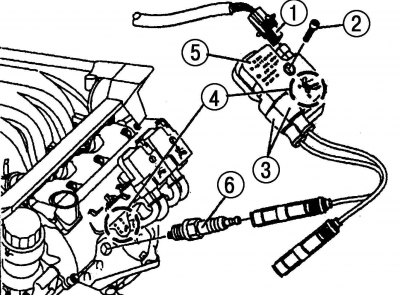
Fig. 5.41. Removing the ignition coil on a V6 engine: 1, 3 – pin connector; 2 – screw; 4 – mounting…

Fig. 5.41. Removing the ignition coil on a V6 engine: 1, 3 – pin connector; 2 – screw; 4 – mounting position; 5 – ignition coil; 6 – spark plug


Disconnect both high-voltage wire connectors from ignition coil 5 (Fig. 5.41).

Note: Pay attention to the installation position 4 marked on the ignition coil and on the engine. The spark plug tips are marked because there are two spark plugs on each cylinder. The connector "a" on the ignition coil must be connected to the tip "K" of the spark plug. Connector "b" - to the tip "G" of the spark plug.


4. Disconnect contact connector 3 from the ignition coil.

5. Unscrew screw 2 and remove the ignition coil.

Installation


6. Install the ignition coil and tighten screw 2.

7. Connect the connector 1.

8. Connect the ignition coil connectors 1.

Attention! Do not mix up the contact connectors, they have marks. Connector "a" on the ignition coil is connected to tip "K" of the spark plug, connector "b" - to tip "G" of the spark plug.


9. Install the mass air flow sensor with the intake pipe.

V8 Engine


Removal


1. Turn off the ignition.
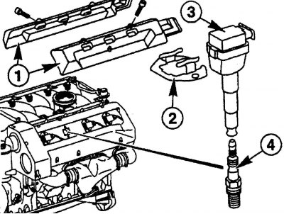
Fig. 5.42. Removing the ignition coil on a V8 engine: 1 – lid; 2 – fastening part; 3 – ignition…

Fig. 5.42. Removing the ignition coil on a V8 engine: 1 – lid; 2 – fastening part; 3 – ignition coil; 4 – spark plug


2. Loosen the mounting bolts and remove covers 1 (Fig. 5.42) from the engine.


3. Disconnect the connectors from the side of each ignition coil.

4. Unscrew the bolts securing part 2.

5. Remove ignition coils 3 from spark plugs 4 by moving them upwards.

Installation


6. Install ignition coils 3 onto spark plugs 4.

7. Tighten the bolts securing part 2.

8. Connect the contact connectors to each coil.

9. Fasten covers 1 to the engine.
This article is available at: russian, bulgarian, belarusian, ukrainian, serbian, croatian, romanian, polish, slovak, hungarian
The article has been verified: Polyakov Zakhar Grigorievich
Share with friends:
◀ Previous
E-Class W210 / Control system
Next ▶

Operation of the engine management system
Safety precautions when working with the engine management system
Engine Management Systems — General Description
Removal and installation the fuel distributor
Removal and installation fuel injectors
Checking the technical condition of fuel injectors
Possible malfunctions of the injection system, their causes and methods of elimination
More similar articles for repairing other models

☛ Ignition switch Mercedes W168 (1997-2004)
☛ Ignition coils — removal and installation Mercedes W202 (1993-2000)
☛ Removal and installation ignition coils Mercedes W463 (1999-2019)
☛ Removal and installation ignition coils — petrol models Mercedes W163 (1997-2005)
☛ Checking and adjusting idle speed/ignition timing/CO concentration Mercedes W140 (1991-1998)
☛ Ignition coils Mercedes Vito 1 (1996-2003)
Link in different formats to this article
Comments and feedback from visitors
No comments yet


How much will 44 + 14 ?


W210 (1996-2002) 
  • General information
  • Vehicle description
  • Working conditions and tools
  • Car care
  • Diesel engines
  • Engine repair
  • Lubrication system
  • Cooling system
  • Injection system
  • Supply system
  • Exhaust system
  • Gasoline engines
  • Engine repair
  • Lubrication system
  • Cooling system
  • Control system
  • Power and exhaust system
  • Transmission
  • Clutch
  • Mechanical gearbox
  • Automatic gearbox
  • Drive shafts
  • Chassis
  • Car suspension
  • Steering
  • Tires and wheels
  • Brake system
  • Body
  • Exterior (external elements)
  • Interior (internal elements)
  • Doors and windows
  • Heating and ventilation
  • Electrical equipment
  • Equipment and devices
  • Power devices
  • Lighting and signaling
  • Electrical circuits
W124 (1984-1995) 
  • General information
  • Governing bodies
  • Driving and operation
  • Weekly care
  • Maintenance (gasoline)
  • Maintenance (diesel)
  • Troubleshooting
  • Power unit
  • I4 petrol engine
  • V6 petrol engine (SOHC)
  • V6 petrol engine (DOHC)
  • Diesel engines
  • Engine overhaul
  • Cooling system
  • Heating and ventilation
  • Fuel system (carburetor)
  • Injection system «Bosch CIS-E»
  • Injection system «Bosch HFM»
  • Diesel fuel system
  • Supply system
  • Starting and charging system
  • Ignition system (I4)
  • Ignition system (V6)
  • Preheating
  • Transmission
  • Clutch
  • Mechanical gearbox
  • Automatic gearbox
  • Drive shafts
  • Chassis
  • Brake system
  • Car suspension
  • Steering
  • Body
  • Exterior (external elements)
  • Interior (internal elements)
  • Doors, locks and windows
  • Electrical equipment
  • Equipment and devices
  • Switches
  • Headlights and lighting
  • Electrical circuits
W123 (1976-1985) 
  • General information
  • Introduction to the guide
  • Power unit
  • Engine device
  • Repair M102 engines
  • Repair M110 and M123 engines
  • Cooling and lubrication (M102)
  • Cooling (M110 and M123)
  • Ignition system
  • Power system «Stromberg»
  • Power system «Solex 4A1»
  • Fuel injection «K-Jetronic»
  • Fuel injection «L-Jetronic»
  • Transmission
  • Clutch
  • Mechanical gearbox
  • Automatic gearbox
  • Cardan and rear axle
  • Chassis
  • Front suspension
  • Rear suspension
  • Steering
  • Brake system
  • Body
  • Exterior (external elements)
  • Interior (internal elements)
  • Doors, locks and windows
  • Electrical equipment
  • Equipment and devices
  • Power devices
  • Electrical circuits
 
MercedesMan.ru © 2017–2026 · Mobile version · Read about Mercedes · Sitemap: EN BG BY UA RS HR RO PL SK HU · Feedback · Site search · Bookmark A-Class (W168) · C-Class (W201) · C-Class (W202) · C-Class (W203) · E-Class (W123) · E-Class (W124) · E-Class (W210) · G-Class (W463) · M-Class (W163) · S-Class (W116, petrol) · S-Class (W126, petrol) · S-Class (W140) · S-Class (W220) · Sprinter · Vito 1 · Vito 2 · Vario 814D ·
 
We only use cookies without which some of the site's features may not be available.