
Attention! Before proceeding with the procedure, read the list of safety measures set out in Section Basic Information and Safety Precautions!
M111
Attention! Before proceeding with the procedure, read the list of safety measures set out in Section Basic Information and Safety Precautions!
Details of installing ignition coils on a 111 series engine are shown in the illustration.
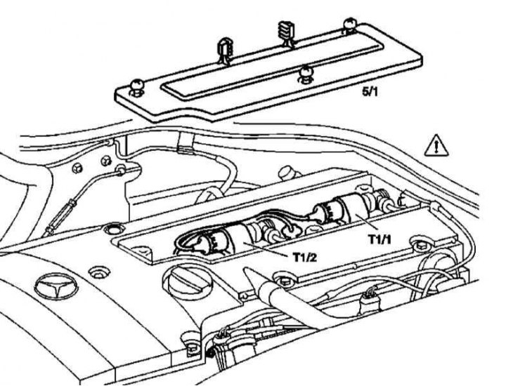
Installation Details for Dual Ignition Coil Modules on a 111 Series Engine
5/1 - Well cover for electrical wiring of ignition coils
T1 / 1 - Module of ignition coils for cylinders No. 1 and 4
T1 / 2 - Module of ignition coils of cylinders No. 2 and 3
M112 and 113
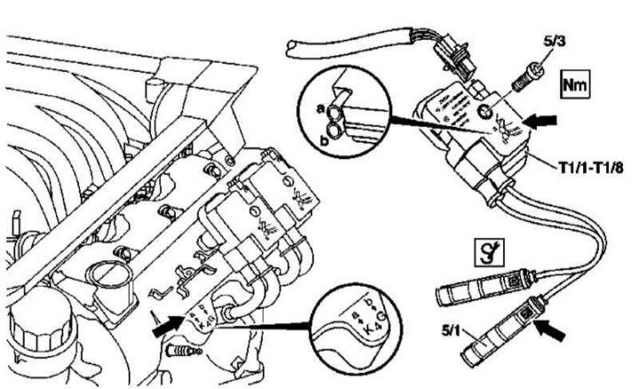
Details of installation of ignition coils on engines of series 112 and 113 (on the example of an 8-cylinder engine)
5/1 - Tip of the candle connector; 5/3 - Bolt; T1 / 1 - Ignition coil of cylinder No. 1; T1 / 2 - Ignition coil of cylinder No. 2; T1 / 3 - Ignition coil of cylinder No. 3; T1 / 4 - Ignition coil of cylinder No. 4; T1 / 5 - Ignition coil of cylinder No. 5; T1 / 6 - Ignition coil of cylinder No. 6; T1 / 7 - Ignition coil of cylinder No. 7; T1 / 8 - Ignition coil of cylinder No. 8; Arrow - Tip identification label
1. Details of the installation of ignition coils on engines of the 112 and 113 series are shown in the illustration, which includes all references in the text.
2. Remove the trim panels of the cylinder head cover/air cleaner.
3. Turn out the fixing pain (5/3).
4. Disconnect the electrical wiring from the appropriate spark plug (5/1).
5. Disconnect the wiring connector and remove the coil assembly (T1/X).
6. Installation is carried out in the reverse order.