



Contents: Operation of the pre-heating device ↡ Glow plugs ↡ Pre-heating time relay ↡ The pre-heating system is faulty ↡ Malfunctions of the pre-heating…↡ Control lamp failure ↡ Monitoring the voltage on the…↡ Checking the current supply to the…↡ Glow plug failure ↡ Defective spark plugs ↡ Replacing glow plugs ↡ Checking glow plugs ↡
In a running diesel engine, the fuel ignites in highly compressed and therefore hot air. During a cold start, self-ignition does not occur, since the self-ignition temperature is not reached. Glow plugs installed on the side in the pre-chamber create an optimal ignition mode when the engine is cold.
Direct injection engines have a significantly shorter warm-up time.
In addition, this device serves primarily to reduce the toxicity of exhaust gases.
Operation of the pre-heating device
The pre-heating device consists of three main units: a glow plug rod, a pre-heating time relay and a control lamp on the instrument panel.
The glow plugs are designed for a voltage of 15 V and are connected in parallel. When the ignition key is turned, a current of about 30 A flows through each plug. The regulating winding in the glow plug reduces the current within about 10 s to 8–15 A. After 10 s of operation, the plugs reach a temperature of +900°C, after 30 s – +1180°C.
The pre-heating time relay determines the pre-heating duration. For this purpose, the relay has a sensor that measures the ambient temperature. At –30°C, the pre-heating time is about 25 sec, at +20°C – about 4 sec, at +40°C – about 2 sec. If the pre-heating is sufficient, the engine readiness control lamp goes out. If the engine does not start after the lamp goes out, the fuse ensures that the current flowing through the spark plugs is disconnected after 20–25 sec. If the engine starts during this time, the pre-heating device is connected again during the rotation of the starter.
Glow plugs
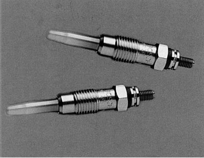
Fig. 4.92. Bosch-Duraterm glow plugs
These are "fast-start rod glow plugs" (Fig. 4.92). The glow plug rod, which enters the pre-chamber, contains one heating and regulating winding behind the other. As the temperature increases, the winding resistance increases. Thus, the current decreases from 30 A to 8–12 A. Each glow plug is controlled separately by the microprocessor of the pre-heating time relay. Additionally, during operation, the plugs are supplied with a small control current. Failure of one or more plugs with the engine running is signaled by a control lamp. When the engine starts, additional heating begins - it lasts up to 180 s, until the coolant temperature reaches +40°C. The purpose of additional heating is to reduce the loud noise during start-up and to improve the exhaust in a cold car. If the temperature sensor on the cylinder head is faulty, additional heating generally lasts 30 s.
At high temperatures, which spark plugs are constantly exposed to, they can fail. This is especially affected by incorrect spray pattern of injectors, too low injection pressure or incorrect injection timing.
Pre-heating time relay
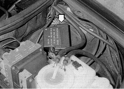
Fig. 4.93. Pre-heating time relay
This relay is installed in the engine near the left wing arch. If you remove the trim, both sockets are visible. The pre-start heating time relay (Fig. 4.93) performs the following functions:
- 1. The power relay regulates the heating current.
- 2. Limiting the amount of current supplied by using an automatic fuse.
- 3. Turning off the indicator lamp when the engine is ready to start.
- 4. The fuse switches off the heating current if the heating remains on for 20-50 s (depending on the ambient temperature).
The pre-heating system is faulty
Malfunctions of the pre-heating system in CDI models can only occur in frost (below -10°C). Only then does the direct injection system have a hard time starting the engine without the "support" of the pre-heating system. A malfunction of the system can be identified by blue exhaust from the muffler.
A malfunction of the pre-heating system is indicated by the fact that the control lamp does not light when the ignition is turned on.
Malfunctions of the pre-heating system
If the engine does not start or starts very poorly when cold, or the glow plug indicator lamp on the instrument panel does not light when the ignition is turned on, the fault must be located and corrected. Start searching with a glow plug indicator lamp or by creating jumpers on certain electrical circuits. The various tests start with both sockets on the glow plug timer relay, which are easily found by removing the cover.
If the control lamp does not light when the heating is turned on, the following faults may occur.
- 1. There is no current at terminal "30" of the pre-heating time relay.
- 2. The power relay is faulty.
- 3. One or more wires on the glow plugs are faulty.
- 4. One or more glow plugs have burned out.
- 5. The control lamp has burned out or its connecting wire is damaged.
Control lamp failure
If the indicator lamp does not light, even though the engine starts well, it may be burnt out.
Article was borrowed from the website: MercedesMan


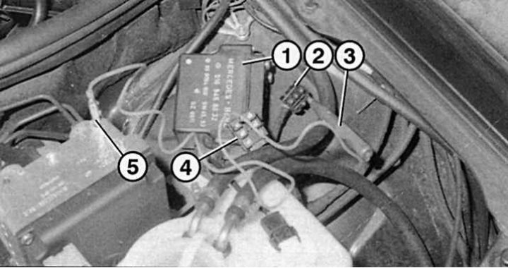
Fig. 4.94. Checking the operation of the pre-heating device indicator lamp: 1 – pre-heating time relay; 2 – temperature sensor and control lamp plug; 3 – control lamp; 4 – glow plug plug; 5 - terminal for connecting the control lamp "to ground"
1. Remove the small plug from the preheating time relay 1 (Fig. 4.94).
2. Turn on the ignition.
3. Connect socket "3" of the plug to the "ground". Now the control lamp should light up.
4. If not, check the wiring to the instrument panel or replace the lamp.
Monitoring the voltage on the pre-heating time relay
If the engine does not start and the preheat indicator lamp does not come on, check the power supply to the preheat time relay.


1. The red wire must always be live (terminal 30).
2. When the ignition is on, there should be a "+" on terminal "15". Check socket 1 on the smaller plug.
3. When the starter rotates, there should also be current at terminal "50" (socket 2).
Checking the current supply to the glow plugs
After the ignition is turned on, current should be supplied to all glow plugs.


1. Disconnect the large plug on the preheat timer relay.
2. Connect the test lamp to ground.
3. Check the current one by one on all relay contacts. After turning on the ignition, each contract should have "+" for the ignition time.
When checking, the assistant must constantly turn the ignition on and off so that the pre-glow mode is always present.
If there is no current coming from the relay, replace the relay.
Glow plug failure
If the control lamp does not light, one of the glow plugs may have burned out. If the engine starts, it does not initially run on all cylinders. In the cylinder without preheating, spontaneous combustion will occur somewhat later.


1. To locate a burnt spark plug, disconnect the large plug from the time relay.
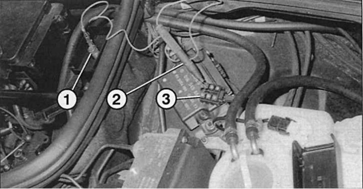
Fig. 4.95. Detecting a faulty spark plug: 1 - "mass"; 2 – control lamp terminal; 3 – socket in the plug
2. Connect one end of the test lamp to the "+" (for example, to the red wire) (Fig. 4.95).
3. Using the other end of the lamp, check the sockets in the plug one by one.
4. Where the indicator lamp does not light, the glow plug is faulty.
Defective spark plugs
1. If there is no test lamp for checking, you can check the spark plug for a "spark".
2. Remove the power plug on the preheating time relay and check the sockets one by one with the wire from the "+". Where there is no spark, the spark plug is faulty.
3. If the preheating system does not work, you can start the engine while towing. The engine may start after 1 km. Try to start the engine while towing at increased engine speed, for example in 2nd gear from 40 km/h (proceed with caution!).
4. If the time relay switches off while driving, stop, connect all the wires to the spark plugs together and connect them to "+" for 10–20 s.
Replacing glow plugs


1. To get to the glow plugs, which are located on the left side of the cylinder head, you need a ratchet wrench with different sockets.
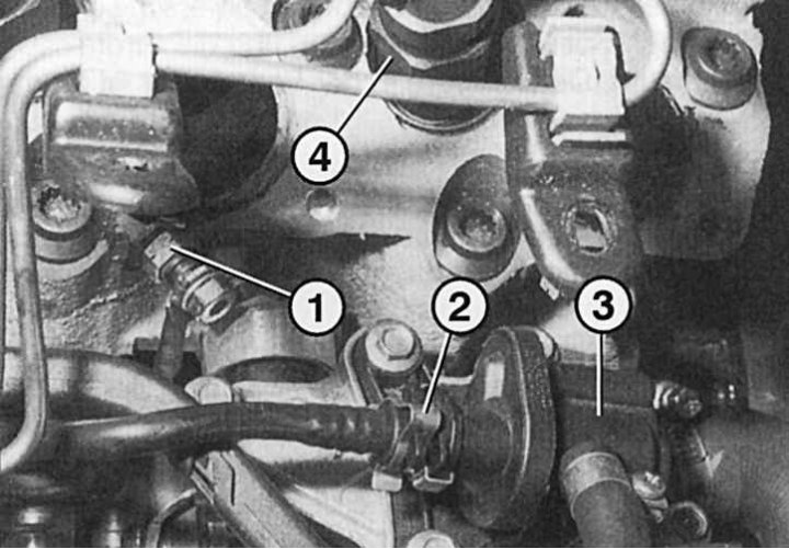
Fig. 4.96. Glow plug location: 1 – glow plug with plug; 2 – fuel line valve on the heat exchanger; 3 – heat exchanger; 4 – nozzle
2. Remove the protective cap on the spark plug (Fig. 4.96).
3. Unscrew the spark plug.
4. Install a new spark plug and tighten to 20 Nm.
Checking glow plugs
The only and most reliable way to check glow plugs is with them turned out.


1. Remove the engine cover if necessary.
2. Disconnect the wires from the glow plugs.
3. Remove the candles and place them on a fireproof surface.
4. Connect the spark plugs one by one using thick wire (minimum 2.5 mm²) and reliable terminals directly to the battery.
5. Check which spark plugs are weak (there are such people too), and some do not sparkle at all.
6. Replace faulty spark plugs. If you want to be absolutely sure that the spark plugs are working, you can replace the entire set.