
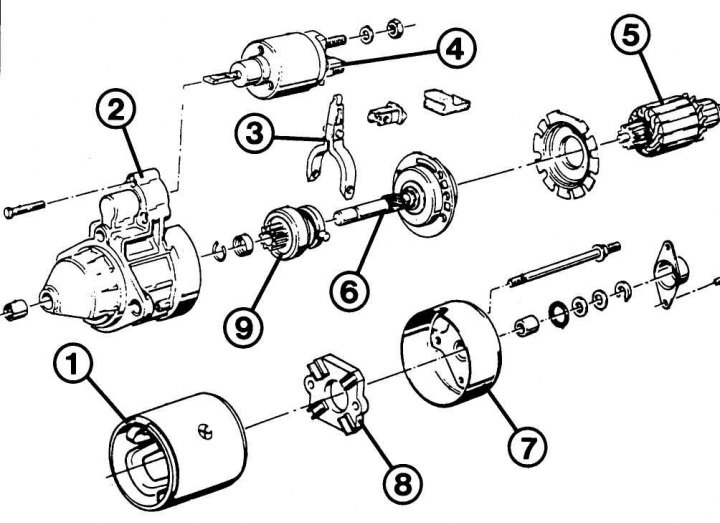
Pic. 9.3. Starter device: 1 - case with winding; 2 - bearing housing; 3 – drive lever; 4 - traction relay; 5 - anchor; 6 - freewheel; 7 – housing cover; 8 - brush holder; 9 - gear
The starter device is shown in fig. 9.3.
1. When the key is turned in the ignition lock to the position «start» from terminal «50» ignition switch, the circuit voltage is supplied to the traction relay located in the upper part of the starter with forced engagement and self-deactivation of the gear.
2. The drive lever attached to the relay moves the starter gear along the armature shaft and engages with the flywheel ring gear.
3. When the gear engages, the magnetic switch supplies voltage from the battery through the main contact. The gear fully engages with the ring gear, and the circuit closes - the starter begins to crank the engine crankshaft.
4. If the engine is started and the key in the ignition switch is released, the magnetic field in the winding of the traction relay disappears. The drive lever is retracted to its original position by a return spring. The gear is disengaged and the power supply to the starter is interrupted.