



Contents: Opening in case of emergency ↡ Vacuum hoses ↡
The infrared control system in combination with the security system is installed as standard on E-Class models. The pneumatic central locking is controlled by switches in the front door locks and the trunk lid. Depending on the signal from the electronic key or the direction of its rotation in the lock, the contacts to the "ground" are closed, and the drive pump receives direct or reverse rotation. In this way, it activates the system, creating pressure or vacuum. The pneumatic central locking works almost silently - there are no clicks of magnets, no buzzing of the electric motor, as is the case with some other cars. The switch on the central console can be used to lock the car from the inside.
Opening in case of emergency
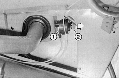
Fig. 10.9. You can gain access to the locking mechanism (1) of the fuel filler flap by removing the right side trim of the trunk. If the flap does not open due to a malfunction in the central locking system, pull the pusher (2) in the direction of the arrow. In this case, an assistant must simultaneously open the flap from the outside
If the central lock fails, the doors open and close mechanically in the usual way. The fuel filler flap can be opened by releasing the locking mechanism, which requires removing the boot trim on the right side (Fig. 10.9).
Pneumatic control mechanism
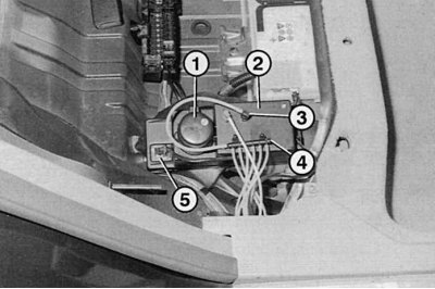
Fig. 10.10. Under the rear seat to the right of the battery, under a separate cover, is the control mechanism for the central locking system: 1 – working pump; 2 – pneumatic accumulator; 3 – vacuum hose with connector; 4 – distributor with contact connectors; 5-pin connector
Working pump 1 (fig. 10.10) system, located in the battery compartment under the rear seat, has the factory designation "pneumatic control mechanism" because it performs other functions. For example, it provides a pressure reservoir (rarefaction), used to drive the adjustments of the orthopedic seat back, as well as the air conditioner. In addition, it serves to support systems using the pressure of the intake system. If, for example, the vacuum in the reservoir has dropped to 400 Mbar, the pump is activated by a switch from the pressure valve and operates until the value of 600 Mbar is established.
If the pump does not turn off, one of the systems is leaky. Depending on the configuration, the car may have up to four pneumatic mechanisms.
Vacuum hoses
The vacuum hoses have contact connectors at the ends, which are used to connect to the pump, door lock drive mechanisms or distribution blocks. The hoses are connected to the doors at the wiring connection points. From the distributor on the pump, the wiring is carried out as follows:
- yellow vacuum hoses lead to the doors and fuel filler flap;
- there is a black hose leading to the trunk lid;
- there is a grey hose leading to the vacuum reservoir in the trunk;
- a transparent hose leads to the distribution block in the engine compartment.