
Removing
Attention! Removing the gearbox is difficult because access to the bolts securing the gearbox to the engine is limited.
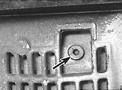
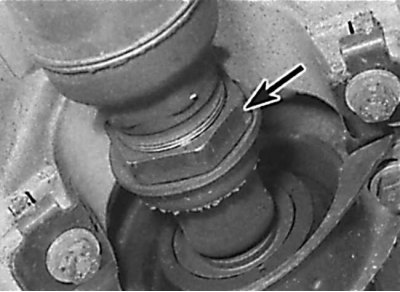
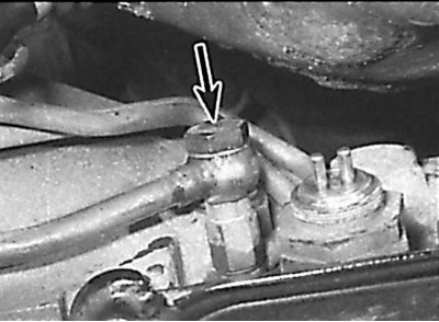
Torque converter drain plug, visible through a window in the gearbox housing
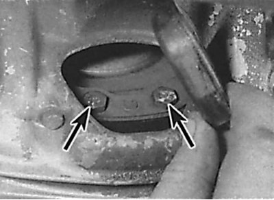
Arrangement of bolts of fastening of the hydrotransformer to a plate of a drive
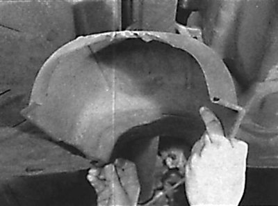
Removing the heat shield from the bottom of the car
Unscrewing the exhaust system mounting bracket from the bottom of the car
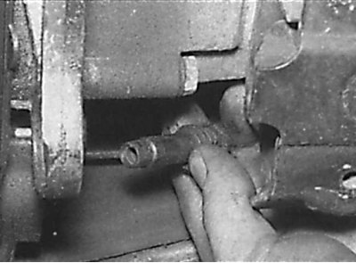
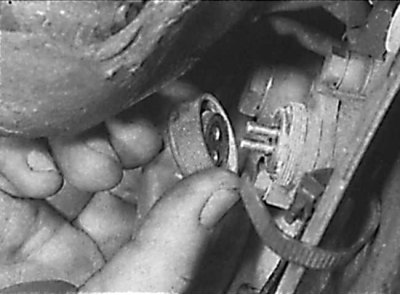
Arrangement of a clamping nut of the central bearing of a cardan shaft
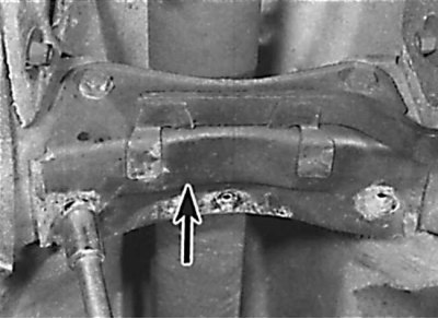
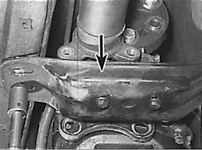
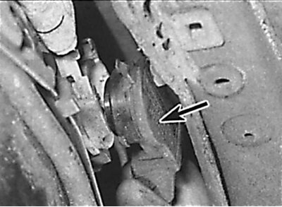
The location of the rear support of the power unit
Disconnecting electrical wires from the traction relay
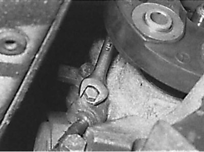
Unscrewing the speedometer cable fastening bolt
Removing the speedometer drive cable from the gearbox housing
An arrangement of an electric socket of the switch of blocking of a starter and lanterns of a backing
Removing the wire from the left side of the gearbox housing
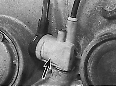
The location of the vacuum chamber on the left side of the automatic transmission
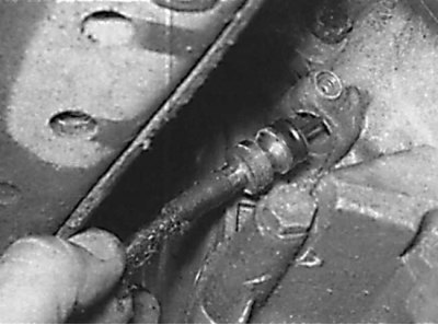
An arrangement of a connecting bolt of fastening of a tube of the heat exchanger of transmission liquid
Removing the pipe for the dipstick for measuring the level of transmission fluid to the gearbox
Unscrewing the bolts securing the gearbox to the engine
When unscrewing the bolts securing the gearbox to the engine, note the location of the ground bus.
Removing the torque converter using additional handles
1. Open the hood and place it in a vertical position. Place a thin sheet of steel on the bulkhead to protect the bulkhead insulation and brake lines when removing the automatic transmission.
2. Remove the ground wire from the battery.
3. On models with an auxiliary heater, when removing the transmission, be careful not to damage the coolant hose located at the rear of the engine compartment. Unscrew the automatic transmission dipstick tube from the cylinder head.
4. Disconnect the automatic transmission pressure control cable from the throttle linkage.
5. Apply the handbrake, then raise the front of the vehicle and support it on stands. The lift height of the vehicle must be sufficient to lower the gearbox and remove it from under the vehicle. Remove the lower engine mudguard.
6. If available, unscrew the bolts securing the cross member located in front of the automatic transmission pan from the bottom of the vehicle. When installing the cross member, new bolts must be used.
7. Place a suitable container under the transmission fluid drain plug, then unscrew the plug and drain the fluid from the automatic transmission.
8. Place a container under the window at the bottom of the gearbox housing. At the pulley bolt, turn the crankshaft until the fluid drain plug from the torque converter appears in the window (see fig. Torque converter drain plug, visible through a window in the gearbox housing).
9. Unscrew the drain plug and drain the fluid from the torque converter.
10. Remove the plastic plug from the clutch housing to access the bolts securing the torque converter to the drive plate (see fig. Arrangement of bolts of fastening of the hydrotransformer to a plate of a drive).
11. Remove the six bolts securing the torque converter to the drive plate by turning the crankshaft in sequence to access the next pair of bolts.
12. Insert a small block of wood between the oil pan and the cross member under the bottom of the vehicle.
13. Remove the exhaust system.
14. If equipped, remove the exhaust heat shield from the underside of the vehicle to gain access to the driveshaft center bearing (see fig. Removing the heat shield from the bottom of the car, Unscrewing the exhaust system mounting bracket from the bottom of the car).
15. Unscrew the brackets for attaching the exhaust system to the bottom of the car, located under the driveshaft. Unscrew bolts and remove an arm of fastening of an exhaust system to a transmission. If equipped, disconnect the electrical wires from the bracket on the gearbox.
16. Disconnect the propeller shaft from the output flange of the automatic transmission.
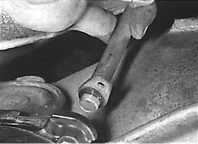
17. Loosen the propeller shaft center bearing nut, then loosen but do not completely unscrew the center bearing housing nuts and move the propeller shaft back until it stops (see fig. Arrangement of a clamping nut of the central bearing of a cardan shaft).
18. Support the automatic transmission with a jack through a wooden block.
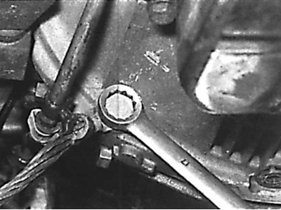
19. Unscrew the rear support of the power unit from the gearbox and the bottom of the car and remove the support (see fig. The location of the rear support of the power unit).
20. Disconnect electric wires from the traction relay in the right back part of an automatic transmission (see fig. Disconnecting electrical wires from the traction relay).
21. Unscrew the fastening bolt and remove the speedometer drive cable from the automatic transmission housing (see fig. Unscrewing the speedometer cable fastening bolt, Removing the speedometer cable from the gearbox housing). If equipped, remove the speedometer cable from the retainers on the transmission.
22. Release the retaining clip and, using two screwdrivers and being careful, remove the electrical connector from the starter and reverse light switch (see fig. An arrangement of an electric socket of the switch of blocking of a starter and lanterns of a backing).
23. Unscrew the special knurled nut and disconnect the wire from the left side of the gearbox housing (see fig. Removing the wire from the left side of the gearbox housing).
24. Disconnect all remaining electrical connectors from the transmission. Remove the electrical wiring from the mounting brackets or brackets on the transaxle case.
25. Disconnect the vacuum tubes from the vacuum chamber on the left side of the gearbox (see fig. The location of the vacuum chamber on the left side of the automatic transmission). Disconnect the remaining vacuum tubes from the gearbox housing. Remove the tubes from the mounting brackets or brackets on the gearbox housing. On some models, to remove the vacuum tubes from the gearbox, you must first disconnect them from the intake manifold in the engine compartment.
26. Remove the mounting brackets and remove the shift rod from the gear select lever on the gearbox and from the bottom of the selector lever.
27. Unscrew the connecting bolts and disconnect the supply and return pipes of the transmission fluid heat exchanger from the gearbox (see fig. An arrangement of a connecting bolt of fastening of a tube of the heat exchanger of transmission liquid). Remove the o-rings and plug the ends of the tubes and the openings in the gearbox to prevent dirt from entering.
28. Unscrew the transmission fluid heat exchanger tube brackets from the transmission from the engine and move the tubes to the side.
29. Release the retaining clip and remove the transmission fluid dipstick.
30. Remove the bolt securing the transmission fluid dipstick tube to the transmission case. If equipped, remove the transmission-to-engine bolt securing the transmission fluid dipstick tube. Remove the transmission fluid dipstick tube from the transmission (see fig. Removing the pipe for the dipstick for measuring the level of transmission fluid to the gearbox, Unscrewing the bolts securing the gearbox to the engine).
31. Remove the starter.
32. Check that the gearbox is securely supported by the jack, then lower it just enough so that the engine rests on a bar inserted between the oil pan and the cross member. When lowering the transmission, be careful not to damage the brake pipes or other elements located on the bulkhead of the engine compartment.
33. Remove the gearbox-to-engine bolts, leaving one bolt on each side of the gearbox. Access to the upper gearbox mounting bolts is very limited. Socket wrenches with extensions and cardan connectors must be used to access these bolts. On some models, the upper gearbox-to-engine bolt is not accessible from below. The top bolt can be accessed from the right side of the engine compartment after doing the following:
- unscrew the heat shields located near the power steering to access the exhaust manifold mounting nuts;
- unscrew the nuts and remove the rear section of the exhaust manifold from the cylinder head. Remove the gasket.
34. Note the location of the ground bus and the brackets fastened with the bolts of the gearbox to the engine.
35. After unscrewing the upper bolts securing the gearbox to the engine, raise the gearbox to its original position.
36. On models with 4- and 5-cylinder diesel engines, when removing the gearbox, it is necessary to secure the torque converter, otherwise it may fall. To do this, through the window in the gearbox housing, insert a steel rod into the hole to drain the oil from the torque converter.
37. Unscrew the remaining bolts securing the gearbox to the engine, then move the gearbox away from the engine and, using a jack, lower and remove the gearbox from under the car. When removing the transmission, be careful not to drop the torque converter.
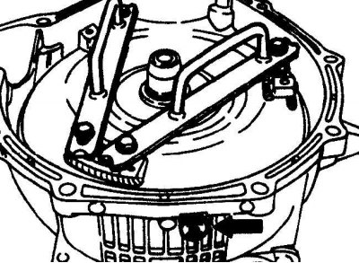
38. Remove the torque converter as follows (see fig. Removing the torque converter using additional handles):
- install the gearbox on wooden blocks in a vertical position with the torque converter up;
- using an 8mm socket wrench, turn the plastic torque converter retainer a quarter of a turn counterclockwise and remove the retainer. On models with 4- and 5-cylinder diesel engines, remove the rod from the torque converter oil drain hole;
- to remove the torque converter, using the long bolts and holes for mounting the drive plate, screw on the two additional handles. Using caution, evenly remove the torque converter from the gearbox housing;
- locate the torque converter in a safe place.
Installation
1. Install the torque converter as follows:
- apply a thin layer of grease to the torque converter drive flange;
- using the additional handles screwed to the torque converter, install it in place. When installing the torque converter, turn it sideways and lift it up and down several times so that the teeth of the torque converter are connected to the input shaft of the gearbox;
- insert the plastic retainer into place and turn it a quarter of a turn clockwise. On 4- and 5-cylinder diesel models, secure the torque converter by inserting a steel rod into the torque converter drain hole;
- rotate the torque converter so that the two bolt holes for the torque converter to the drive plate are located at the bottom of the gearbox.
2. Using a jack through a wooden beam, lift the gearbox into place.
3. Move a transmission before connection of a case of a transmission to the block of cylinders.
4. Bolt the gearbox to the engine, while installing the ground bar and brackets that are attached with these bolts.
5. Screw in the bolts securing the torque converter to the drive plate and tighten them to the required torque. To access each subsequent pair of bolts, turn the engine crankshaft.
6. Further installation is carried out in the reverse order of removal, taking into account the following points.
7. When installing the transmission fluid heat exchanger pipes, use new O-rings.
8. Connect the propeller shaft to the gearbox flange.
9. Check up correctness of connection to a transmission of electric sockets and vacuum hoses.
10. Install the exhaust system.
11. Fill the transmission with transmission fluid.
12. Check and, if necessary, adjust the pressure control cable.