
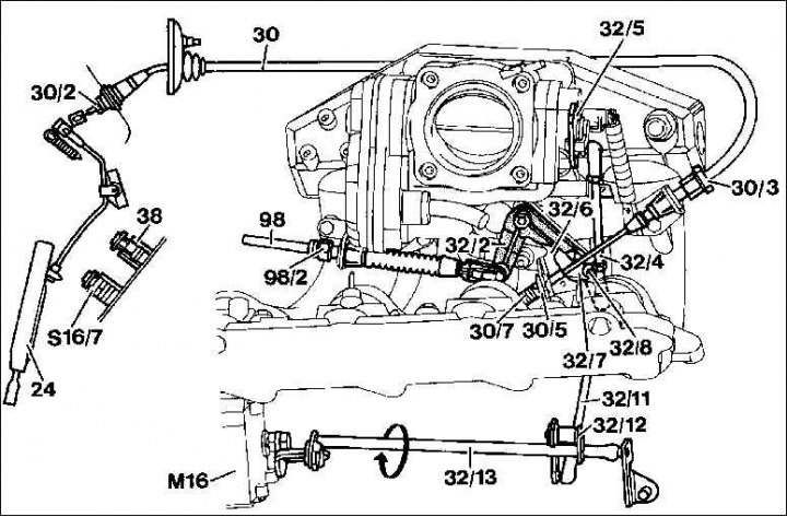
Throttle cable adjustment (30)
1. With the engine stopped and the accelerator pedal not depressed, between the drive spring (30/7) and guide element (30/5) there must be a gap of 0.5 to 1.0 mm, otherwise set it with the adjusting screw (30/3).
2. crank arm (32/5) must be in contact with the throttle valve idle speed limiter, otherwise change the connecting rod (32/4). The connecting rod must be set very precisely. The microswitch in the idle position must be pressed (closed).
3. Video clip (32/8) without tension must lie against the end stop of the adjusting lever (32/7). Otherwise, adjust the connecting rod accordingly (32/4).
4. Adjust Bowden cable to set pilot pressure (98). To do this, turn the set screw (98/2) until the tip of the rocker arm (32/2) will not mount at the same height as the tip of the rocker arm (32/6).
5. With the engine stopped, instruct a partner to press the accelerator pedal to the stop of the throttle lever, fix the latter in the position of maximum fuel supply. For automatic transmission, do not operate the accelerator pedal switch (S16/7).
6. Check that the throttle shaft lever is in contact with the throttle lever stop. Automatic transmission: otherwise, turn the set screw accordingly (30/3). Manual speed transmission: Adjust throttle lever stop.
Throttle lever stop adjustment in footwell (only in case of manual transmission)
1. Disengage the footwell throttle lever stop by turning it to the left and pull out the locking bolt a little.
2. Slowly depress the accelerator pedal to the maximum fuel delivery position until the throttle lever rests against its stop.
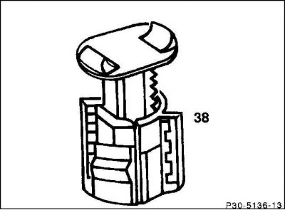
3. Lock the throttle lever in this position (38) through its rotation to the right side in the inner space.
4. Release the accelerator pedal (24). Between the driving spring (30/7) and guide element (30/5) there must be a gap of 0.5 to 1.0 mm, otherwise, in the interior of the car, adjust using the adjusting nut (30/2).
5. Lubricate the Bowden cable with anti-corrosion grease between the tip and the guide (30/5).
6. If so, check the tempomat adjustment.
Tempomat adjustment
1. Unhook the connecting rod (32/11) on one side of the spherical head.
2. Adjustment lever (32/7) must be in neutral.
3. Turn the adjusting shaft (32/13) the executive body of the tempomat (M16) in clockwise direction (in the direction of the arrow). In this case, the executive body is in a neutral position.
4. Turn the adjusting shaft (32/13) the executive body of the tempomat (M16) in clockwise direction (in the direction of the arrow). In this case, the executive body is in a neutral position.
5. Then reattach the connecting rod. In this case, the lever of the executive body must be raised by about 1 mm from the stop of the throttle lever.
6. Otherwise, adjust the connecting rod. Press out the spherical insert. Loosen the lock nut and screw in or out the spherical bushing, tighten the lock nut again.