



The pump cavity contains an eccentrically mounted rotor with a series of slotted grooves evenly spaced around the circumference. Freely sliding metal plates - blades - are installed in these slots. When the rotor rotates, the plates, under the action of centrifugal force, come out of the slots and come into contact with the walls of the pump cavity. The injection occurs due to the change in volume enclosed between pairs of adjacent blades. This change in volume occurs due to the eccentricity of the rotor installation. Such pumps develop pressure of about 8-13 MPa (80-130 bar).
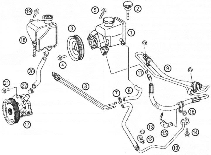
VN 6.004 The figure shows two types of hydraulic power steering pumps that can be installed 1. Hydraulic pump (with internal oil tank); 2. Oil tank cap with oil level dipstick; 3. Pulley; 4. Bolt; 5. Bolt; 6. Hose; 7. Clamp; 8, Cooling coil; 9. High pressure line; 10. Tube; 11. Sealing ring; 12. Clamp; 13. Nut; 14. Bolt; 15. Bracket; 16. Nut; 17. Hydraulic pump (with a separate oil tank); 18. Oil tank; 19. Bolt; 20. Hose; 21. Bolt; 22. Clamp
Original material on the website MercedesMan.ru