
Removing
1. Remove the air intake 10 (see fig.9.2).
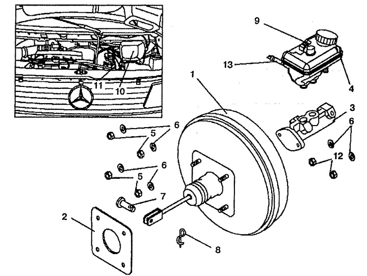
Pic. 9.2. Vacuum brake booster:
1. Vacuum amplifier,
2. Gasket,
3. Master cylinder,
4. Brake fluid reservoir,
5. Nut M8,
6. Washers,
7. Bolt,
8. Cotter pin,
9. Brake fluid level sensor wiring connector,
10. Air intake,
11. Vacuum tube,
12. Nuts,
13. Tube to the main brake cylinder.
2. Remove the main brake cylinder 3.
3. Remove vacuum tube 11 from vacuum booster 1.
4. Remove the cover under the instrument panel (on model 638.2 and right hand drive models).
5. Loosen the bolt 7 that secures the vacuum booster 1 to the brake pedal.
6. Loosen the four nuts 5 securing the vacuum booster 1 to the pedal bracket.
7. Remove vacuum booster 1.
Installation
8. Installation is made in an order, the return to removal. When installing the vacuum booster 1, do not pinch the wiring of the brake fluid level sensor.
Examination
9. Connect tester 030 to vacuum booster 1 (see fig.9.3).
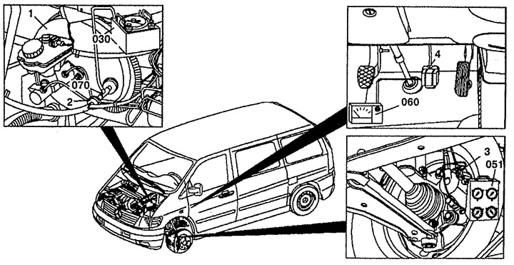
Pic. 9.3. Checking the vacuum booster:
1. Vacuum amplifier,
2. Shut-off valve,
3. 070. Adapter,
4. Brake pedal,
030. Tester,
051. Pressure gauge,
060. A device for measuring the force on the brake pedal.
10. Attach pressure gauge 051 to adapter 3 on the brake mechanism using a clamp.
11. Install the device 060, which measures the force of pressing the brake pedal, on the brake pedal 4.
12. Start the engine, depress and release the accelerator pedal to create a vacuum. If the vacuum does not reach the required value or decreases rapidly, check the toroidal ring between the vacuum booster and the brake master cylinder. Check the shutoff valve and, on vehicles with 601 engines, check the vacuum pump.
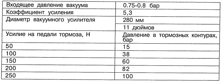
13. Press a brake pedal with a certain effort and measure vacuum. The pressure values in the brake circuits depending on the vacuum are presented in table 9.1.
Table 9.1. Pressure values in the brake circuits as a function of the vacuum.
14. Disconnect all connected devices and bleed the brake system.