
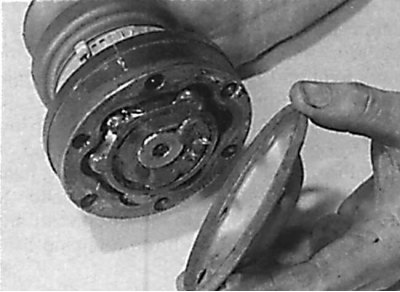
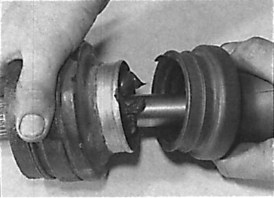
Removing the protective cover from the end of the inner CV joint
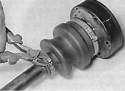
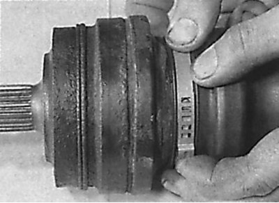
Removal of collars of fastening of a protective cover of SHRUS
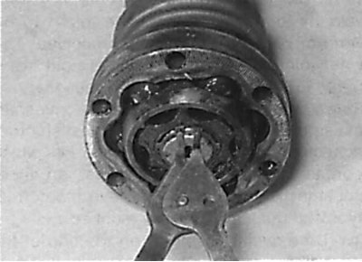
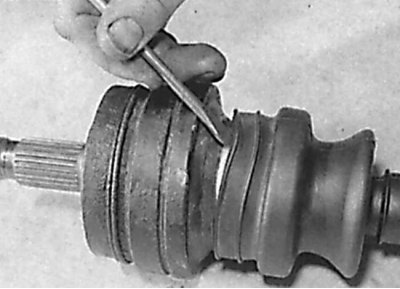
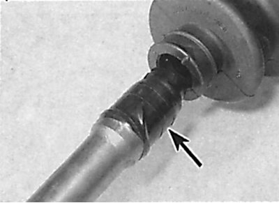
Removing the retaining ring securing the inner CV joint to the drive shaft
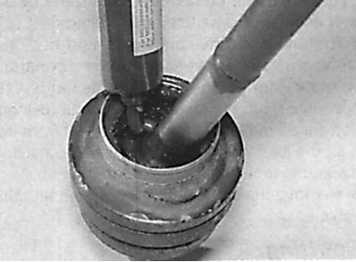
Filling with grease constant velocity joint
Installing a new protective cover on the CV joint
Raising one of the edges of the protective cover to equalize the pressure inside the cover with atmospheric
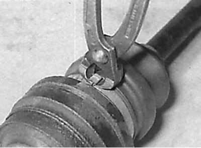
Installation of a collar of fastening of a protective cover of SHRUS
Final tightening of the clamp for fastening the protective cover of the CV joint
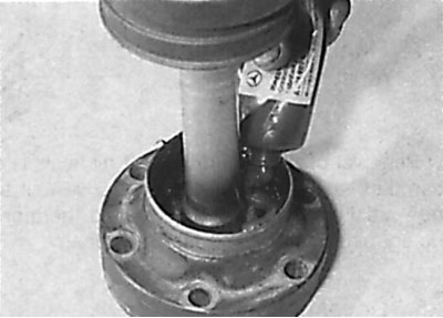
Installing a new protective cover of the inner CV joint on the drive shaft
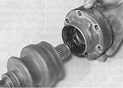
Installing the inner CV joint on the drive shaft
Filling the internal cavities of the CV joint with lubricant
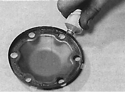
Applying a layer of lubricant to the inner end of the protective cover
1. Remove the drive shaft.
2. Clean the drive shaft and secure it in a soft jaw vise.
3. Remove the protective cover from the end of the inner CV joint (see fig. Removing the protective cover from the end of the inner CV joint).
4. Remove the two clamps securing the protective cover of the inner CV joint and slide the protective cover onto the drive shaft (see fig. Removal of collars of fastening of a protective cover of SHRUS).
5. Clean out the grease and remove the inner CV joint retaining ring from the end of the drive shaft (see fig. Removing the retaining ring securing the inner CV joint to the drive shaft).
6. While holding the inner CV joint and using a hammer and drift, knock the drive shaft out of the joint. If the CV joint is too tight on the shaft, a puller may be required. Do not disassemble the inner CV joint.
7. Remove the protective cover by sliding it over the drive shaft.
8. Remove the clamps securing the protective cover of the outer CV joint and remove it by sliding it along the shaft.
9. Using an appropriate solvent, clean the CV joints and wipe them dry.
10. Sequentially turn the hinge hub so that the balls in turn are at the top. Check the balls for cracks, deformation or pitting.
11. Check the condition of the ball tracks. If the treadmills are broken, the movement of the balls along them will be uneven. Check the holes in the cage for wear and cracks. If necessary, replace the protective covers of the CV joints. Before installing the covers, clean the mating surfaces of the CV joint and the cover and apply a thin layer of grease to the cover.
12. If at least one of the parts of the CV joint is worn out, it is necessary to replace the CV joint assembly. The replacement of the inner CV joint can be done separately, and the outer CV joint is replaced only as an assembly with the drive shaft. When assembling, it is necessary to use new protective boots, new collars for fastening protective boots, a new retaining ring of the drive shaft inner joint and lubricant.
13. Tape the splines on the end of the drive shaft with adhesive tape.
14. Slide the new outer joint boot over the drive shaft.
15. Fill the cavities of the outer CV joint with the required amount of lubricant. By moving the hinges, evenly distribute the lubricant. Fill the inner cavity of the protective boot with the same lubricant (see fig. Filling with grease constant velocity joint).
16. Install the protective boot on the CV joint and check that the protrusions of the protective boot are correctly seated on the drive shaft and the CV joint housing. Using a screwdriver blade, pry up one end of the protective case in order to equalize the pressure inside the protective case with atmospheric pressure (see fig. Installing a new protective cover on the CV joint, Raising one of the edges of the protective cover to equalize the pressure inside the cover with atmospheric).
17. Place a large tie-wrap on the protective cover, tighten it and snap it into position. Using special pliers, finally tighten the clamp securing the drive shaft protective boot. Install the second clamp securing the protective cover in the same way (see fig. Installation of the clamp for fastening the protective cover of the CV joint, Final tightening of the clamp for fastening the protective cover of the constant velocity joint).
18. Slide the new inner CV joint boot over the drive shaft (see fig. Installing a new protective cover of the inner CV joint on the drive shaft).
19. Remove the adhesive tape covering the splines of the drive shaft. Install the inner CV joint on the drive shaft, press it and secure it with a new circlip (see fig. Installing the inner CV joint on the drive shaft).
20. Fill the internal cavity of the CV joint with lubricant, as well as the inside of the protective cover (see fig. Filling the internal cavities of the CV joint with lubricant).
21. Install the protective boot on the CV joint and check that the protrusions of the protective boot are correctly installed on the drive shaft and the CV joint housing. Using a screwdriver blade, lift one end of the protective case to equalize the pressure inside the case with atmospheric pressure.
22. Place a large tie-wrap on the protective cover, tighten it and snap it into position. Using special pliers, finally tighten the clamp securing the protective cover. Install the second clamp securing the protective cover in the same way.
23. Clean the mating surfaces of the CV joint and the protective cover and apply a thin layer of lubricant to the inner end of the protective cover (see fig. Applying a layer of lubricant to the inner end of the protective cover).
24. Install the protective cover on the end of the inner hinge. Check the smooth movement of the hinges, then install the drive shaft.