
Cars BMW Cars Volkswagen Cars Chevrolet Cars Land Rover Cars Lada Cars Honda Cars Peugeot
English Русский
Български
Беларускі
Український
Српски
Hrvatski
Română
Polski
Slovenský
Magyar
Bookmark News and articles Sitemap Feedback Site search
MercedesMan.ru


A-Class C-Class E-Class G-Class M-Class S-Class Others
190 (W201) (1982-1993) W202 (1993-2000) W203 (2000-2007)
  • Main
  • C-Class
  • W203 (2000-2007)
  • Transmission
  • Clutch and drive shafts
  • Disassembling drive shafts and replacing protective covers

Disassembling drive shafts and replacing protective covers (Mercedes-Benz C-Class W203)

0
Contents: Disassembly ↡ Assembly ↡
The outer constant velocity joint is not disassembled. If there is any damage, replace the shaft entirely. Both covers are removed from the inside. It is recommended to replace both covers during long-term use.

Disassembly


1. Remove the rear drive shaft, refer to the relevant section.
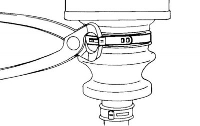
2. Loosen the threaded clamps, cut the tie clamps and replace them with threaded ones during…


2. Loosen the threaded clamps, cut the tie clamps and replace them with threaded ones during installation.

3. Remove the inner joint boot cover from the housing and move it towards the drive shaft as follows:
  • Clamp the drive shaft in a vice;
  • Use a hacksaw to cut the cover of the case at an angle of about 45° to create a corner groove.

Caution! Be careful not to damage the hinge housing;

  • Use a screwdriver to lift the notched top slightly;
  • Use tweezers to grasp the protruding end of the cover and screw it on until the cover separates from the hinge housing.

Caution: When screwing on, make sure that the drive shaft does not fall out of the joint ring unless the parts are marked.


4. Wipe off the grease from the hinge with a rag.
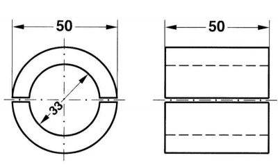
5. Press the drive shaft out of the inner joint using a press. Use half rings as a lining, which…


5. Press the drive shaft out of the inner joint using a press. Use half rings as a lining, which rest on the joint flange. The half rings have the following dimensions:


  • Outer diameter 50 mm,
  • Inner diameter 33 mm,
  • Length 50 mm.

6. Remove the inner joint boot from the drive shaft.

7. If necessary, remove the outer joint boot clamps, remove the boot cover and remove the boot through the shaft. Make sure that no dirt gets into the joint. Before removing the boot, remove the grease from the inside of the boot and inject it into the joint.

8. If necessary, wash the joint in gasoline and check the raceways for wear and damage. If there is severe wear, the entire joint must be replaced.

9. Clean the rear drive shaft.

Assembly


1. To replace the protective cover, use the repair kit. In case of long-term use, it is recommended to also replace the second cover.
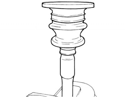
2. Place the mounting sleeve on the splines of the drive shaft. If such a sleeve is not available,…


2. Place the mounting sleeve on the splines of the drive shaft. If such a sleeve is not available, cover the splines with protective film to avoid damaging the cover.

3. Install the new outer seal ring.

4. Put on the outer cover and clamps.

5. Place the inner cover and clamps on the drive shaft.

6. Install the new inner sealing ring.

7. Remove the mounting sleeve and protective film.

8. Place the inner joint on the shaft.
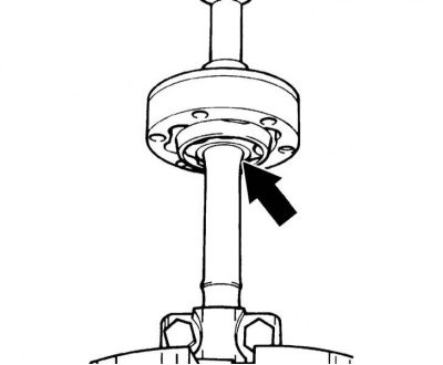


9. Clamp the shaft in the area of the boot flange using a clamping device or in a vice with…


9. Clamp the shaft in the area of the boot flange using a clamping device or in a vice with protective jaws.

10. Press the constant velocity joint with a drift until it rests against the mating surface of the rear drive shaft. Then press the joint until the rear drive shaft protrusion is 4.2 mm.

11. Clamp the shaft in a vice so that the joint hub fits against the half rings. Fix the shaft with a chasing. At the same time, make a new chasing in the middle between the two existing ones. For chasing, use the appropriate tool with a working part 5-6 mm wide.

To avoid damage to the raceways, for example due to tool rebound, it is necessary to carry out the chasing as close to the splines as possible.

12. Remove the clamping device.

13. Place the cover of the cover onto the corresponding hinge ring until it stops.

Caution! Do not lubricate the sealing ring, otherwise the cover will later rotate on the hinge ring. If necessary, the ring can be put back in place with light blows from a plastic hammer.


14. Fix the boot cover with four blows in a circle with a step of 90° in the groove of the hinge housing. Then pull the cover with a hammer into the groove of the hinge housing. At the same time, make sure that the boot cover is correctly positioned.


15. Fill the cavities and boots of the inner and outer constant velocity joints with 100 g of MERCEDES grease. Make sure that no dirt gets into the joints.

16. Place the protective cover on the lid so that the sealing lip of the cover is located between the lip of the cover cover.

17. Put the small diameter boots on the thickening of the drive shaft so that the groove of the drive shaft is not visible after installation. The thickening of the boot is thus fixed in the first groove of the shaft. Put on the clamps and secure them.

Attention! The clamp screws must face in the same direction. On the second cover, install the clamps so that they are offset by 180° relative to the first cover.


18. Install the drive shaft.
This article is available at: russian, bulgarian, belarusian, ukrainian, serbian, croatian, romanian, polish, slovak, hungarian
The article has been verified: Rodionov Artyom Semyonovich
Share with friends:
◀ Previous
C-Class W203 / Clutch and drive shafts
Next ▶

Removal and installation wheel drive shafts
Design and description of wheel drive shafts
Removal and installation the propeller shaft
Bleeding the clutch drive, replacing the hydraulic fluid
Clutch — removal, inspection and installation
 
More similar articles for repairing other models

☛ Clutch drive — bleeding air and replacing fluid in the hydraulic drive Mercedes W168 (1997-2004)
☛ Replacing the rear wheel drive shaft protective cover Mercedes W123 (1976-1985)
☛ Disassembling the input (drive) shaft Mercedes W463 (1999-2019)
☛ Removal and installation drive shafts Mercedes W163 (1997-2005)
☛ Checking the condition of the protective covers of the drive shafts Mercedes W140 (1991-1998)
☛ Replacing tie rod ends and protective covers Mercedes Sprinter (1995-2000, diesel)
Link in different formats to this article
Comments and feedback from visitors
No comments yet


How much will 11 + 44 ?


W203 (2000-2007) 
  • General information
  • Introduction to guide
  • User manual
  • Maintenance
  • Power unit
  • Gasoline engines
  • Diesel engines
  • Cooling system
  • Ventilation and heating
  • Supply system
  • Injection system (gasoline)
  • Injection system (diesel)
  • Exhaust system
  • Ignition and control system
  • Charge and launch systems
  • Transmission
  • Mechanical gearbox
  • Automatic gearbox
  • Clutch and drive shafts
  • Differential
  • Chassis
  • Brake system
  • Car suspension
  • Steering
  • Body
  • Exterior (external elements)
  • Interior (internal elements)
  • Electrical equipment
  • Equipment and devices
  • Lighting system
  • Electrical diagrams (2000)
  • Electrical diagrams (since 2001)
W202 (1993-2000) 
  • General information
  • User manual
  • Driving a car
  • Car care
  • Maintenance
  • Power unit
  • Gasoline engines
  • Diesel engines
  • Lubrication system
  • Cooling system
  • Heating and ventilation
  • Ignition system
  • Fuel system
  • Injection system (gasoline)
  • Injection system (diesel)
  • Exhaust system
  • Transmission
  • Clutch
  • Car gearbox
  • Chassis
  • Suspension, wheels and tires
  • Steering
  • Brake system
  • Body
  • Exterior (external elements)
  • Interior (internal elements)
  • Doors and windows
  • Electrical equipment
  • Equipment and devices
  • Power devices
  • Lighting system
  • Electrical circuits
190 (W201) (1982-1993) 
  • General information
  • Introduction to the guide
  • Operation and care
  • Maintenance (gasoline)
  • Maintenance (diesel)
  • Troubleshooting
  • Power unit
  • Petrol engine I4
  • Petrol engine V6
  • Diesel engines
  • Engine overhaul
  • Cooling and heating
  • Power system (carburetor)
  • Injection system (gasoline)
  • Injection system (diesel)
  • Exhaust system
  • Charge and start system
  • Ignition system (I4)
  • Ignition system (V6)
  • Diesel heating system
  • Transmission
  • Clutch
  • Mechanical gearbox
  • Automatic gearbox
  • Cardan shaft and axle shafts
  • Chassis
  • Brake system
  • Car suspension
  • Steering
  • Body
  • Exterior (external elements)
  • Interior (internal elements)
  • Doors, locks and windows
  • Electrical equipment
  • Equipment and devices
  • Electrical circuits
 
MercedesMan.ru © 2017–2026 · Mobile version · Read about Mercedes · Sitemap: EN BG BY UA RS HR RO PL SK HU · Feedback · Site search · Bookmark A-Class (W168) · C-Class (W201) · C-Class (W202) · C-Class (W203) · E-Class (W123) · E-Class (W124) · E-Class (W210) · G-Class (W463) · M-Class (W163) · S-Class (W116, petrol) · S-Class (W126, petrol) · S-Class (W140) · S-Class (W220) · Sprinter · Vito 1 · Vito 2 · Vario 814D ·
 
We only use cookies without which some of the site's features may not be available.