
Note. If the outer CV joint located on the wheel side is damaged, the corresponding shaft must be completely replaced.
Removing
1. Apply the parking brake.
Attention! When loosening the wheel nut, the vehicle must be with its wheels on the ground. Shift into gear, apply the brake. Big turning point. There is a danger of an accident!
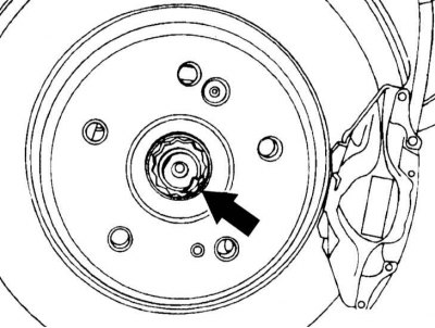
2. Bend the shoulder of the wheel nut out of the groove of the shaft with a screwdriver. Loosen the nut with a hex head.
3. Release the parking brake.
4. Mark with paint the position of the rear wheels relative to the hub. This will allow you to install the balanced wheels in their original position during assembly. Loosen the wheel bolts before jacking up the vehicle. Raise the rear of the car, put it on stands and remove the rear wheels.
5. Disconnect the rear caliper and secure it with a wire to the body, refer to Section Removal and installation of a back support.
Attention! Do not disconnect the brake hose. Otherwise, after installation, air will have to be removed from the brake system.
6. Remove the connecting rod that goes to the stabilizer.
7. Disconnect the speed sensor from the knuckle.
8. Disconnect steering draft from a fist.
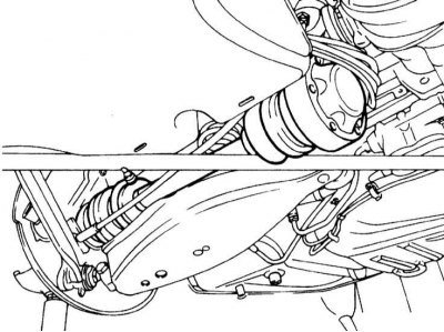
9. Tilt the knuckle outward and at the same time push the drive shaft out of the flange.
Attention! At the same time, do not overtighten the brake cable. Do not damage the protective covers and the gear ring of the speed sensor.
10. Fold back your fist and secure with wire.
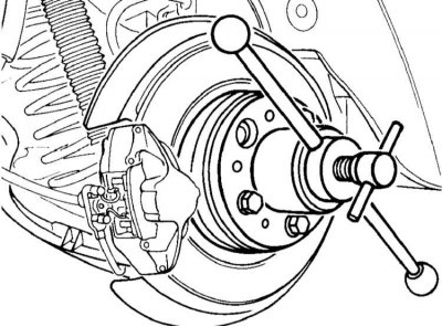
11. If the drive shaft is tightly seated in the flange, squeeze it out with a conventional puller.
Note. Unlike the one shown in the accompanying illustration, the caliper is removed.
Drive shaft version 1
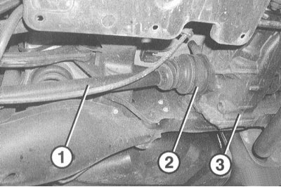
1. Remove the drive shaft (1) with internal hinge (2) from main gear (3).
Attention! Do not damage the sealing ring in the main gear.
Note. If necessary, remove the drive shaft by hammering on the outer ring of the hinge and using a suitable drift.
2. Visually check up damages of a cuff in the main transfer, if necessary replace.
Note. To do this, squeeze out the cuff with a screwdriver. Before installing, lubricate the seal lip with SAE 85W-90 Hypoid Multipurpose Oil. Press in the collar with a suitable punch.
Drive shaft version 2
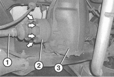
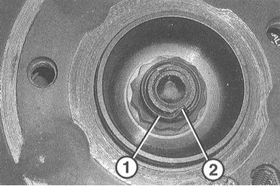
1. Remove the 6 Torx screws and disconnect the drive shaft (1) from connecting flange (2). (3) - main gear.
Attention! Make sure the socket is in the correct position in the head of the Torx screw. If necessary, clean the profile of the Torx screw.
2. Slide the drive shaft, then tilt down and remove.
Attention! Make sure that the locking cover does not come off when removing the shaft.
3. Check the protective cover and sealing cap for leaks and damage and repair if necessary.
Attention! With the drive shaft removed, the vehicle must not stand on its wheels with a full load and must not move, because. If there is no axial tension, the rolling elements of the wheel bearing can be damaged.
Installation
Attention! If, when removing the drive shaft, it is necessary to apply a lot of force necessary to extrude the wheel hub, it is recommended to cut an internal thread M8 with a depth of 20 mm at the end of the shaft. A disassembly tool can be screwed into this hole. Depending on the design of the drive shaft, it may have a hole with a diameter of 6.8 mm, which corresponds to the inner diameter of the M8 thread. Before installation, clean the profile of the splines from grease residues.
Option 1 drive shaft: Insert the shaft into the final drive until the circlip clearly engages.
Attention! At the same time, install the hinge housing horizontally so as not to warp the splined shaft during installation. The hinge housing must be located tightly to the final drive housing.
Drive shaft version 2
1. Clean the area between the connecting flange and the sealing cover.
2. Install the shaft at the connecting flange.
3. Lightly lubricate the threads and bearing surface of the head of the new Torx screws.
4. Install a new washer and screw in the Torx screws. Tighten the screws crosswise with a torque of 70 Nm.
5. Fasten the tie rod and rods with new self-locking nuts.
Attention! When tightening the nuts, the drive shaft must be brought to a horizontal position. To do this, raise the wheel holder with a jack.
The tightening torques are given in Specifications.
6. Fix the speed sensor at the knuckle with a torque of 8Nm.
7. Insert the connecting rod of the stabilizer and secure it with a torque of 40Nm.
8. Install the caliper and fix it with a torque of 55Nm, refer to Section Removal and installation of a back support.
9. Reinstall the rear wheels so that the marks made during removal match. Pre-lubricate with a thin layer of bearing grease the centering belt of the wheel disk on the hub. Do not grease wheel bolts. Replace rusty bolts. Wrap bolts. Lower the car onto the wheels and tighten the bolts crosswise to 110Nm.
10. Apply the parking brake.
11. Fit a new hex collar nut and tighten to 220Nm.
Attention! In this case, the car must stand with its wheels on the ground. The nut must be replaced with a new one. While tightening, shift into gear and apply the parking brake.
12. Fix the nut by driving the collar into the groove with a drift so that there is no gap between the groove and the collar.
13. Release the parking brake.
14. Check the oil level in the final drive.