



Contents: Removal ↡ Installation ↡
Attention! When installing the propeller shaft, it is necessary to use new nuts for fastening the front and rear parts of the propeller shaft.
Removal
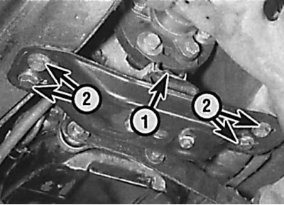
Location of the nut securing the rear of the bracket to the gearbox (1) and the bolts (2) securing the bracket to the underbody
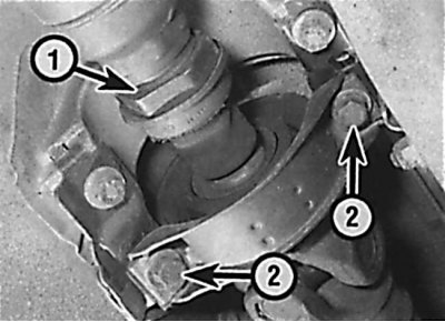
Location of the nut (1) of the splined coupling of the cardan shaft and bolts (2) of the central bearing fastening
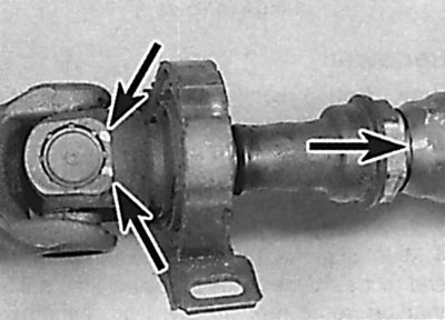
Location of alignment marks on both parts of the drive shaft
1. Raise the rear of the vehicle and support it on stands.
2. Unscrew and remove the exhaust heat shield. If necessary, unscrew and remove the brackets installed across the driveshaft tunnel.
3. Place a jack under the gearbox and lift it up so that the weight of the power unit is supported by the jack.
4. Unscrew the nut securing the rear of the bracket to the gearbox and the bolts securing the bracket to the underbody and remove the bracket (see fig. Location of the nut securing the rear part of the bracket to the gearbox and the bolts securing the bracket to the bottom of the body).
5. Using a spanner, loosen the splined coupling nut located near the center bearing by two turns, being careful not to damage the rubber protective boot (see Fig. Location of the cardan shaft spline coupling nut and central bearing mounting bolts).
6. Apply alignment marks to the flexible coupling of the cardan shaft and the output flange of the gearbox. Then unscrew the nuts and remove the bolts securing the flexible coupling to the output flange of the gearbox. New nuts must be used for installation.
7. Apply alignment marks to the flexible coupling of the cardan shaft and the flange of the rear final drive. Unscrew the nuts and remove the bolts securing the flexible coupling to the rear final drive. New nuts must be used for installation.
8. Support the propeller shaft and remove the center bearing bracket mounting bolts. Move the rear of the propeller shaft forward and disconnect the propeller shaft from the rear final drive flange. Disconnect the front of the propeller shaft from the gearbox output flange and remove the propeller shaft.
Full article available on the resource [MercedesMAN.ru]
Important! If the drive shaft is to be disassembled, first apply alignment marks to both parts of the cardan shaft. This is necessary for the correct assembly of the cardan shaft, since otherwise the shaft balance will be disturbed, which will cause vibration and additional noise during movement. Some models already have alignment marks applied to both parts of the cardan shaft. The mark on the front part of the cardan shaft should be installed in the middle of the marks on the universal joint (see fig. Location of alignment marks on both parts of the drive shaft).
9. Check the condition of the rubber elastic couplings of the central bearing and universal joint.
Installation
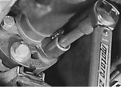
Tightening the nuts securing the cardan shaft coupling to the gearbox flange
1. On models with a shaft bushing located on the gearbox and a bronze shaft end, lubricate the bushing with molybdenum disulfide lubricant. If the bushing is not bronze, use a general-purpose grease.
2. Install the cardan shaft in place, aligning the marks on the elastic couplings of the cardan shaft with the marks on the output flange of the gearbox and the flange of the rear main gear. Secure the central bearing bracket with bolts, without tightening them completely.
3. Check the alignment of the marks, then insert the bolts securing the flexible coupling of the cardan shaft to the rear main gear and screw on new nuts, tightening them to the required torque.
4. Check the alignment of the marks, then insert the bolts securing the flexible coupling of the cardan shaft to the output flange of the gearbox, screw new nuts onto them and tighten to the required torque (see fig. Tightening the nuts securing the cardan shaft coupling to the gearbox flange).
5. Tighten the center bearing bracket mounting bolts to the specified torque.
6. Check that the propeller shaft protective rubber boot is correctly installed and tighten the spline coupling nut to the specified torque.
7. Install the rear transmission mounting bracket and tighten the nut and bolts to the specified torque.
8. Install the exhaust heat shield and brackets, then lower the vehicle.