



Contents: EZL Ignition System ↡ Ignition system TFZ ↡
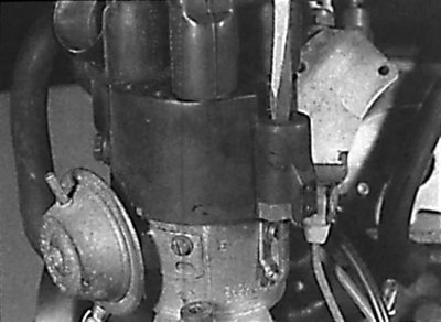
To remove the distributor cap on models with the TFZ ignition system, turn the cover mounting screws a quarter turn.
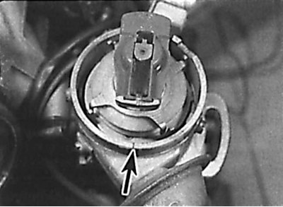
Alignment of the distributor rotor with the mark on the ignition distributor housing
EZL Ignition System
Removal
1. The ignition distributor is installed in a vertical position on the side of the cylinder block.
2. Remove the ground cable from the battery.
3. Set the piston of the first cylinder to the top dead center as follows. Unscrew the screws, lift and move the distributor cap to the side without disconnecting the high-voltage wires from it. Determine the location of the installation mark on the distributor housing, which is a small recess on the upper edge of the distributor housing.
4. Using the crankshaft pulley mounting bolt, turn the engine crankshaft in the direction of operating rotation until the distributor rotor electrode aligns with the mark on the distributor housing.
5. Continue to rotate the engine crankshaft until the top dead center mark on the vibration damper aligns with the pointer on the timing chain cover.
Caution! Align the alignment mark with the pointer very precisely.
6. Check that the distributor rotor is aligned precisely with the mark on the distributor housing. If the distributor rotor is turned 180° from the mark on the distributor housing, the piston of the first cylinder is at top dead center on the exhaust stroke. In this case, turn the engine crankshaft one full revolution and align the timing mark on the vibration damper with the pointer on the drive chain cover.
7. The ignition distributor can now be removed and installed without disturbing the ignition timing angle, provided that the engine crankshaft is not turned.
8. Unscrew the mounting bolt and remove the distributor housing from the cylinder block.
9. Check the condition of the sealing ring and replace it if necessary.
Installation
1. If the engine crankshaft was turned after removing the ignition distributor, perform the following steps.
2. Remove the spark plug from the number one cylinder. Cover the spark plug hole with your thumb and turn the engine crankshaft until your finger feels pressure in the cylinder. Continue turning the engine crankshaft until the top dead center mark on the vibration damper aligns with the pointer on the timing chain housing.
3. Insert the ignition distributor into the cylinder block and align the distributor shaft with the drive so that the distributor rotor aligns with the mark on the ignition distributor housing. The ignition distributor housing must fit neatly onto the mounting flange of the cylinder block, and the hole in the mounting flange for the ignition distributor mounting bolt must be positioned in the center of the groove in the base of the distributor housing. If necessary, rotate the distributor housing.
4. Secure the distributor housing with the bolt, tightening it to the required torque.
5. Install the distributor cap and secure it with screws.
Ignition system TFZ
Removal
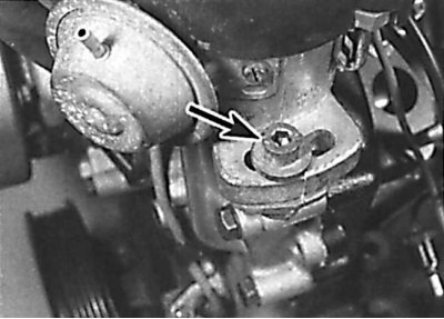
Location of the ignition distributor mounting bolt on models with the TFZ ignition system
1. The ignition distributor is installed in a vertical position on the side of the cylinder block.
2. Remove the ground cable from the battery.
3. Set the piston of the first cylinder to the top dead center as follows. Turn the screws of the ignition distributor cap a quarter of a turn, lift and move the ignition distributor cap to the side without disconnecting the high-voltage wires from it. Determine the location of the installation mark on the ignition distributor housing, which is a small recess on the upper edge of the ignition distributor housing.
4. Using the crankshaft pulley mounting bolt, turn the engine crankshaft in the direction of operating rotation until the distributor rotor electrode aligns with the mark on the distributor housing.
5. Continue to rotate the engine crankshaft until the top dead center mark on the vibration damper aligns with the pointer on the timing chain cover.
Caution! Align the alignment mark with the pointer very precisely.
6. Check that the distributor rotor is aligned precisely with the mark on the distributor housing. If the distributor rotor is turned 180° from the mark on the distributor housing, the piston of the first cylinder is at top dead center on the exhaust stroke. In this case, turn the engine crankshaft one full revolution and align the timing mark on the vibration damper with the pointer on the drive chain cover.
7. The ignition distributor can now be removed and installed without disturbing the ignition timing angle, provided that the engine crankshaft is not turned.
8. Remove the hose from the vacuum regulator located on the side of the distributor housing.
9. Disconnect the electrical connector of the pulse sensor from the side of the ignition distributor housing.
10. Using paint, mark the position of the distributor housing relative to the mounting flange.
11. Unscrew the mounting bolt and remove the distributor housing from the cylinder block (see Fig. Location of the ignition distributor mounting bolt on models with the TFZ ignition system).
12. Check the condition of the sealing ring and replace it if necessary.
Installation
1. If the engine crankshaft was turned after removing the ignition distributor, perform the following steps.
2. Remove the spark plug from the number one cylinder. Cover the spark plug hole with your thumb and turn the engine crankshaft until your finger feels pressure in the cylinder. Continue turning the engine crankshaft until the top dead center mark on the vibration damper aligns with the pointer on the timing chain housing.
3. Insert the ignition distributor into the cylinder block and align the distributor shaft with the drive so that the distributor rotor aligns with the mark on the ignition distributor housing. The ignition distributor housing must fit neatly onto the mounting flange of the cylinder block, and the hole in the mounting flange for the ignition distributor mounting bolt must be positioned in the center of the groove in the base of the distributor housing. If necessary, rotate the distributor housing.
4. Secure the distributor housing with the bolt, tightening it to the required torque.
5. Install the distributor cap and secure it with screws.
6. Connect the hose to the vacuum regulator and the electrical connector of the pulse sensor.
7. Check and, if necessary, adjust the ignition timing.