



Attention! Checking the wheel alignment angles is mandatory if replacement or repair of suspension parts is carried out, which may lead to a change in the wheel alignment angles.
Before adjusting the wheel alignment angles, check:
- tire pressure;
- axial clearance in front wheel hub bearings;
- serviceability of shock absorbers;
- radial and axial runout of wheel disks;
- clearances in the upper and lower ball joints of the suspension;
- serviceability of silent blocks;
- steering wheel free play;
- no play in the steering rods.
Correct any detected faults and make the necessary adjustments.
Immediately before adjustment, the following conditions must be met:
- the car must be complete, with a full fuel tank, spare wheel and a set of tools;
- the steering wheel is set to the center position;
- "press" the front and rear parts of the car 2-3 times from top to bottom with a force of 40-50 kgf.
The order of checking and adjusting the wheel alignment angles:
- 1. Angle of longitudinal inclination of the axis of rotation.
- 2. Camber angle.
- 3. Convergence.
Wheel camber angle and front strut angle
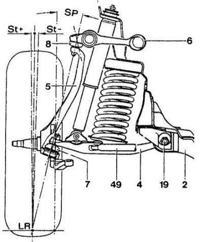
St - camber angle; SP - Front pillar tilt; LR - rolling shoulder; 2 - cross beam; 4 - lower wishbone; 7 - ball joint; 8 - upper ball joint; 19 - eccentric pin for changing wheel camber; 49 - auxiliary thrust
Longitudinal angle of inclination of the wheel pivot axis
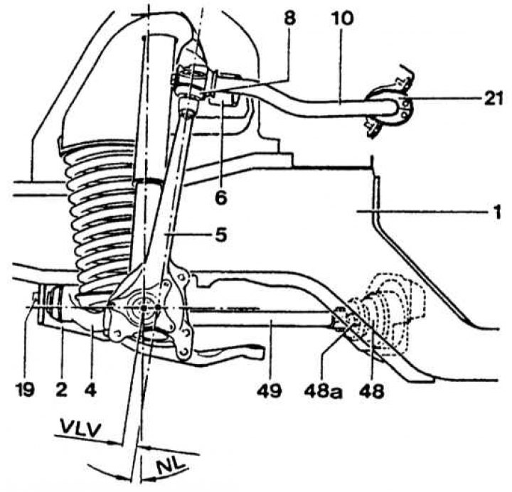
NL - longitudinal inclination angle of the wheel pivot axis; VLV - forward wheel rotation axis runout; 1 - longitudinal beam; 2 - cross beam; 4 - lower wishbone; 5 - rotary stand; 6 - upper wishbone; 8 - upper ball joint; 10 - stabilizer; 19 - eccentric pin for changing wheel camber; 21 - rubber bushing of stabilizer; 48a - auxiliary traction joint; 48 - terminal clamp for changing the length of the auxiliary traction; 49 - auxiliary thrust
The longitudinal inclination angle of the wheel pivot axis is adjusted by auxiliary rod 49 and must be within the range of 8°45'±30°. The difference in the longitudinal inclination angles of the left and right wheel pivot axis must not exceed 0°30'.
The camber angle of the wheels is adjusted by the eccentric pin 19 and should be within 0°120'.
When adjusting the caster and camber, their mutual influence must be taken into account. When the caster angle changes by 0°30' in the minus direction, the camber angle changes by approximately 0°10' in the minus direction. When the camber changes by 0°10' in the minus direction, the caster angle changes by approximately 0°10' in the plus direction. Therefore, after adjusting the camber, it is necessary to check the caster angle and vice versa.
The front wheel alignment is adjusted by the tie rods. To adjust, loosen the tie rod clamps and turn the couplings to the required value. Wheel alignment (the front wheels are compressed with a force of 9-11 kgf.) 0°25'±10' or 3±1 mm. After adjustment, set the clamping clamps horizontally and tighten them in this position. When the nuts are tightened, the edges of the slots of the clamping clamps should not touch.