



Contents: Removal ↡ Installation ↡
Removal
Attention! Removing the gearbox is complicated by the fact that access to the bolts that secure the gearbox to the engine is limited.
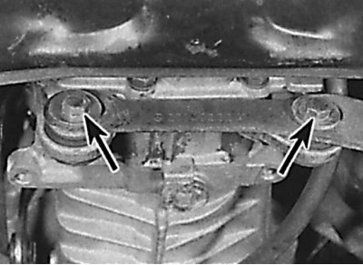
Location of exhaust pipe support bracket mounting bolts
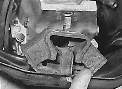
Removal the rear engine/gearbox mount
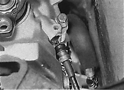
Removal the speedometer drive cable from the gearbox
1. Open the hood and set it in a vertical position. Install a thin sheet of steel on the engine compartment bulkhead to protect the bulkhead insulation and brake system pipes from damage.
2. Remove the ground cable from the battery.
3. On models with auxiliary heater, when removing the transmission, be careful not to damage the coolant supply hose located at the rear of the engine compartment. Unscrew the transmission oil dipstick tube from the cylinder head.
4. Raise the front of the car and secure it on stands. Remove the engine splash shield.
5. Drain the oil from the gearbox.
6. Place a small block of wood between the oil pan and the cross member underneath the vehicle.
7. Remove the exhaust system.
8. If present, remove the exhaust system insulation from the underbody of the vehicle to access the driveshaft intermediate bearing.
9. Unscrew the exhaust system mounting brackets from the bottom of the vehicle (under the cardan shaft). Unscrew the two bolts and remove the exhaust pipe mounting bracket from the gearbox (see Fig. Location of exhaust pipe support bracket mounting bolts). If present, remove the electrical wires from the bracket on the transmission.
10. Disconnect the propeller shaft from the gearbox output flange.
11. Loosen the intermediate bearing mounting nut of the propeller shaft, then loosen, but do not unscrew, the intermediate bearing housing mounting nuts and move the propeller shaft all the way back.
12. Support the gearbox with a jack through a wooden block.
13. Unbolt the rear engine/transmission mount from the underbody of the vehicle and transmission and remove the mount from underneath the vehicle (see Fig. Removing the rear engine/gearbox mount).
14. Unscrew the mounting bolt and remove the speedometer drive cable from the gearbox (see Fig. Removing the speedometer drive cable from the gearbox).
15. Unscrew the clutch slave cylinder from the gearbox and, without disconnecting the hydraulic tube from it, move it back from the gearbox. Remove the plastic gasket.
Caution! On some models, removing the clutch slave cylinder together with the hydraulic tube does not provide enough space to remove the gearbox. In this case, before removing the clutch slave cylinder, it is necessary to disconnect the hydraulic hose from it and drain the fluid from the clutch hydraulic system.
16. Working underneath the vehicle, remove the mounting brackets and disconnect the shift rods from the gear selector levers.
17. Remove the starter.
18. Make sure the transmission is securely supported by the jack, then lower it until the engine rests on a block inserted between the oil pan and the crossmember. When lowering the transmission, be careful not to damage the brake pipes or other components located on the engine compartment bulkhead.
Article text obtained from the website: MercedesMan
19. Remove the transmission-to-engine mounting bolts, leaving one bolt on each side of the transmission. Access to the upper transmission mounting bolts is very limited. Socket wrenches with extensions and universal joints must be used to access these bolts. On some models, the upper transmission-to-engine mounting bolt is not accessible from below. Access to the upper bolt is possible from the right side of the engine compartment after performing the following steps:
- unscrew the heat shields located near the power steering to access the exhaust manifold mounting nuts;
- unscrew the nuts and remove the rear section of the exhaust manifold from the cylinder head. Remove the gasket.
20. Mark the location of the ground bus and the brackets that are secured with the transmission-to-engine mounting bolts.
21. After unscrewing the upper bolts securing the gearbox to the engine, lift the gearbox to its original position.
22. Remove the remaining two transmission-to-engine bolts, then move the transmission away from the engine to remove the transmission input shaft from the clutch disc. The transmission input shaft should not hang on the clutch when moving the transmission. Be careful not to damage the clutch slave cylinder and hydraulic line when doing this.
23. After the gearbox input shaft has disengaged from the clutch, carefully lower the gearbox and remove it from under the vehicle.
Installation
1. Check and, if necessary, center the clutch disc.
2. Before installing the gearbox, check for lubrication on the clutch release mechanism.
3. Check the condition of the bearing at the end of the crankshaft.
4. Lubricate the transmission input shaft splines with a thin layer of molybdenum disulfide grease.
5. Place the gearbox on a jack using a wooden block and lift it into place.
6. When lifting the gearbox, check that the clutch slave cylinder with the hydraulic pipe are not pinched between the gearbox and the vehicle body.
7. Move the gearbox toward the engine, with the gearbox input shaft lining up with the clutch disc. You may need to rotate the engine crankshaft slightly to align the gearbox input shaft splines with the clutch disc splines. The input shaft should not hang on the clutch disc when installing the gearbox.
8. Move the gearbox forward until the clutch housing is seated on the engine block. If necessary, rotate the gearbox until the gearbox mounting bolt holes are aligned with the holes in the engine.
9. Secure the gearbox with bolts. At the same time, check that the ground bus and the brackets that secure the same bolts are in place.
10. Further installation is carried out in the reverse order of removal, taking into account the following points.
11. If necessary, install the exhaust manifold with a new gasket.
12. If necessary, bleed the clutch hydraulic system.
13. Connect the propeller shaft to the gearbox output flange.
14. Install the exhaust system.
15. Fill the gearbox with oil.