



Contents: Removal ↡ Installation ↡
Note: Since this work requires some experience, only the basics required by an experienced mechanic are described. The description applies to a diesel engine. Notes regarding a gasoline engine are given at the end of the section.
Removal
1. Disconnect the negative (-) battery cable with the ignition off. The cabin air filter box must be removed first.
Warning! Before disconnecting the cable, find out the radio receiver security code, if any, refer to Section Replacing the battery.
The operation of lifting and installing the car on stands is associated with danger! Therefore, before carrying out the operation, read the Section Jacking and towing Introduction to the manual.
2. Raise and place the vehicle on stands.
3. Remove the lower engine compartment cover, refer to the relevant section.
4. Drain the coolant, refer to Section Coolant Replacement - General Notes.
5. Disconnect the generator connector.
6. Disconnect the turbocharger at the lower bracket.
7. Disconnect the oil sensor connector.
8. Remove the top engine covers, refer to the relevant section.
9. Remove the air filter, refer to Section Removal and installation the air filter.
10. Disconnect the oil level indicator guide pipe holder at the rear right of the cylinder head.
11. Disconnect the connectors of the glow plugs, coolant temperature sensor, fuel pressure sensor and cylinder head pressure regulating valve.
12. Disconnect the ground wire near the electrically controlled shut-off valve at the cylinder head.
13. Disconnect the cable holder near the cylinder head pressure regulating valve.
14. Remove the thermostat housing, refer to Section Removal and installation the thermostat.
15. Remove the injectors, refer to Section Removal and installation injectors.
16. Remove the cylinder head cover, refer to the relevant section.
17. Remove the chain tensioner, refer to Section Removal and installation the chain tensioner.
18. Set the piston of the first cylinder to the TDC position, refer to the relevant section.
Caution! Do not rotate the engine in the opposite direction. Never rotate the engine by the camshaft sprocket mounting bolt.
19. Remove the front cover from the cylinder head, refer to the relevant section.
20. Remove the upper guide, refer to the relevant section.
21. Remove the camshafts, refer to the relevant section.
22. Remove the camshaft housing.
23. Remove the fuel injection pump.
24. Remove the intermediate sprocket, refer to the relevant section.
25. Remove the air distributor.
26. Remove the oil supply line to the turbocharger.
27. Remove the coolant hose to the generator.
28. Disconnect the pre-catalytic converter from the cylinder block.
29. Disconnect the turbocharger from the exhaust manifold.
Note: The exhaust manifold remains attached to the cylinder head.
30. Remove the bolts securing the cylinder head to the timing mechanism housing cover.
31. Remove the cylinder head mounting bolts in reverse order of numbering, i.e. from 12 to 1 (4-cylinder engine) or from 14 to 1 (5-cylinder engine). In this case, first unscrew all the bolts by ½ turn and then unscrew the bolts.
32. With the help of an assistant, lift the cylinder head. At the service station, the head is lifted using an electric hoist or a shop crane. To do this, grab the cables by the two eyes on the exhaust manifold.
Installation
Before installing the cylinder head and block, remove any remaining sealant from the mating surfaces with a scraper. Make sure that no sealant remains in the holes. Cover the holes with rags. Remove the rags after cleaning.
1. Check the flatness of the block and cylinder head surfaces in the longitudinal and transverse directions with a steel ruler; if necessary, treat the surfaces (work of the service station).
2. Check the cylinder head for cracks and the cylinder running surfaces for grooves.
3. Thoroughly clean the cylinder head bolt holes from oil and other products. Blow out the holes with compressed air or remove the oil with a screwdriver wrapped in a rag.
Caution! The holes for the cylinder head mounting bolts must be free of oil and coolant residues. Otherwise, when screwing in new bolts, pressure will be created that can lead to destruction of the cylinder block or to an incorrect assessment of the tightening torque.
4. Be sure to replace the cylinder head gasket.
5. Place the new gasket in place without sealant, being careful not to block any openings.
6. Install the cylinder head with the help of an assistant. Make sure that the cylinder head is not tilted during installation.
Attention! The cylinder head on the cylinder block is centered by guide bushings.
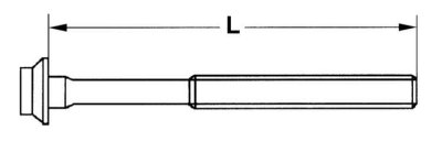
7. Measure the length of the cylinder head bolts. The length of new bolts is 102 mm. Each time the bolts are tightened, they become longer. When the length reaches 104 mm or more, the bolts must be replaced.
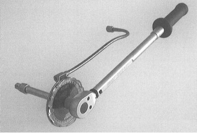
8. Lubricate the threads and the bearing surface of the bolt head with oil and screw them in by hand until they fit against the head.
Attention! Tightening of cylinder head mounting bolts should be done with special care. Before tightening, check the accuracy of the torque wrench. Tightening of bolts to a specified angle should be done using an angle washer, for example, HAZET 6690. To avoid overloading the torque wrench with a high torque, use an angle washer with a regular wrench.
Note: If you don't have an angle washer, you can estimate the angle another way. To do this, place a rigid wrench so that the handle of the wrench is along the engine and turn the wrench in one go so that the handle is positioned across the engine.
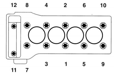
9. Tighten the cylinder head bolts in three stages, in the sequence 1 through 10 as specified in the Specifications.
10. Tighten the Torx screws (11) and (12) securing the cylinder head to the timing case cover to a torque of 20 Nm.
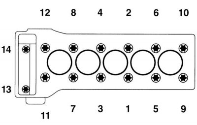
11. Tighten the cylinder head bolts in five steps, in the sequence specified in the Specifications.
12. Secure the turbocharger to the exhaust manifold with a torque of 30 Nm.
13. Secure the pre-catalytic converter to the cylinder block.
14. Install the coolant line to the generator.
15. Secure the oil supply line with new gaskets to the turbocharger with a torque of 30 Nm and to the cylinder head with a torque of 22 Nm.
16. Install the air distributor.
17. Install the intermediate sprocket, refer to the relevant section.
18. Install the injection pump. Secure the high-pressure line at the injection pump and the line with a torque of 22 Nm.
19. Install the camshaft housing.
20. Install the camshafts, refer to the relevant section.
21. Install the top guide, refer to the relevant section.
22. Install the front cover on the cylinder head, refer to the relevant section.
23. Install the chain tensioner with a new sealing ring, refer to Section Removal and installation the chain tensioner.
24. Install the cylinder head cover, refer to the relevant section.
25. Install the injectors, refer to Section Removal and installation injectors.
26. Install the thermostat housing, refer to Section Removal and installation the thermostat.
27. Secure the cable holder near the pressure regulating valve on the cylinder head.
28. Secure the ground wire near the electrically controlled shut-off valve on the cylinder head.
29. Connect the connectors of the glow plugs, coolant temperature sensor, fuel pressure sensor and cylinder head pressure regulating valve.
30. Secure the transmission oil level indicator guide tube holder to the rear right of the cylinder head.
31. Install the air filter, refer to Section Removal and installation the air filter.
32. Install the upper engine covers, refer to the relevant section.
33. Connect the oil sensor connector.
34. Tighten the lower bracket to the turbocharger with a torque of 30 Nm.
35. Connect the generator connector.
36. Install the lower engine compartment cover, refer to the relevant section.
37. Lower the car onto its wheels.
38. Check the engine oil level.
39. Fill the system with coolant, refer to Section Coolant Replacement - General Notes.
40. Connect the negative (-) cable to the battery with the ignition off. Reinstall the cabin air filter box. Enter the radio code and set the clock.
41. Check the engine for leaks in terms of oil and coolant. Check the cooling system for leaks when the engine reaches operating temperature.
Note: The cylinder head gasket only becomes airtight when the engine warms up to operating temperature and the gasket swells accordingly.