
Attention! External constant velocity joint (SHRUS) - inseparable. Both cuffs are placed on the inside of the shaft. After a long period of use, it is recommended to replace the cuffs.
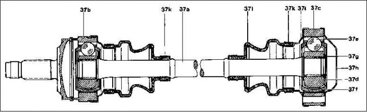
37a. half shaft; 37b. External CV joint; 37c. Internal CV joint; 37d. Hinge hub; 37e. Ball; 37f. Separator; 37g. retaining ring; 37h. Lid; 37i. Cap cuff; 37k. collar; 37l. Cuff
Removing
1. Remove the half shaft.
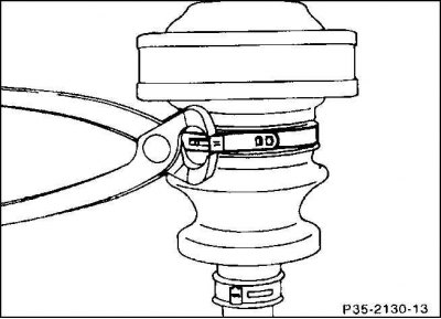
2. Unscrew the screw clamp, bite the clamp clamp and subsequently replace it with a screw clamp.

3. Knock off the shaft cover with a punch.
4. Remove the cuff from the hinge to the axle shaft.
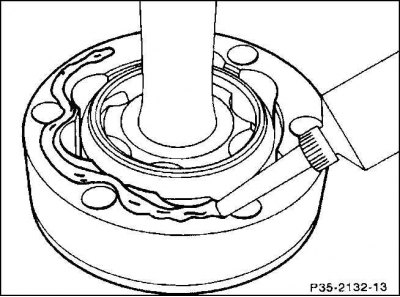
5. Wipe off the grease on the hinge with a rag.
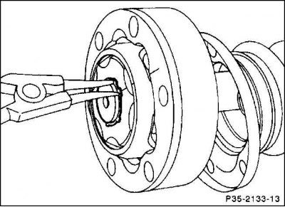
6. Using expandable round nose pliers, expand the retaining ring and remove it.
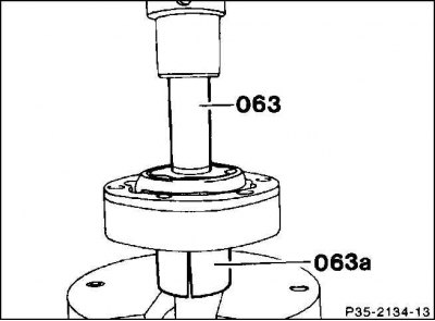
7. Press the axle shaft out of the inner CV joint. To do this, use the appropriate punch (063) (length approx. 80 mm), as well as a split sleeve (063a).
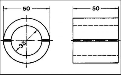
8. The split sleeve can be made independently according to the specified drawing.
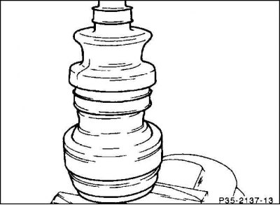
9. Remove the rubber cuff of the inner CV joint from the axle shaft.
10. If necessary, loosen the collar of the outer cuff and remove it through the axle shaft. Make sure that dirt does not get into the hinge. Before removing the cuff, remove the grease from its inside and lay it in the CV joint. If necessary, wash the inner CV joint in gasoline and inspect the ball cages for wear. If there are signs of severe wear and grooves, replace the entire joint.
11. Clean the half shaft.
Installation
1. Use a repair kit to change the cuff, which consists of one retaining ring, four clamps, one rubber cuff and 100 g of long-term grease MB for the hinge (for 1 hinge). On vehicles that have been used for a long time, it is recommended to immediately change both cuffs. Put a sleeve on the shaft splines to protect the cuff from damage during assembly, and in the absence of such a sleeve, wrap the splines with adhesive tape.
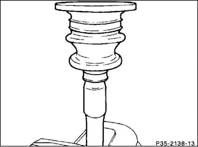
2. Put on the outer cuff, then the inner cuff. After that, remove the auxiliary sleeve or adhesive tape.
3. Slide the inner joint onto the axle shaft.
4. Clamp the axle shaft in the fixture or between the protective jaws of the vise at the shoulder of the cuff.
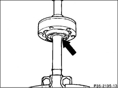
5. Press the CV joint with a suitable punch to the stop (arrow) on the half shaft.
6. Release the axle shaft from the clamp. Install the new retaining ring, making sure it fits correctly in the slot.
7. Fill the joints and seals with the prescribed amount of Mercedes-Fliessfett genuine fluid lubricant (see table).
8. Lubricate the contact surfaces of the inner CV joint with the cover and rubber collar with a sealant such as Curil, Loctite 574 or Hylomar.
9. Put on the cover and rubber cuff.
10. Fasten the cuffs with screw clamps on the CV joints and the axle shaft. On the semi-axis, the cuffs must be pulled over the shoulder to the CV joint. Install the axle.
Attention! The screws of the clamps should, if possible, have the same direction, for which sit the clamps turned to each other by 180°C.
| Hole diameter of the inner CV joint, mm | 86 | 94 | 102 |
| The amount of lubricant for the inner CV joint, g | 100 | 120 | 150 |
| The amount of lubricant on the outer CV joint, g | 100 | 120 | 150 |