



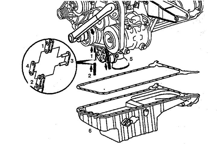
Figure 2.82. Replacing the oil pump drive chain:
1. Old chain,
2. New chain,
3. Intermediate link,
4. Outer cover,
5. Oil pump,
6. Pallet.
2. Disconnect the old oil pump drive chain 1. To do this, knock off the heads of the link bolts before removing the chain (arrow) (see figure 2.83). Using a screwdriver (arrow), disconnect the chain by removing one of the links and pressing out the outer cover 3 (see figure 2.84).
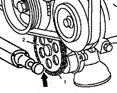
Figure 2.83. Knock off the link bolt heads before removing the chain (arrow).

Figure 2.84. Disconnect the chain by removing one of the links and pressing out the outer cover 3.
3. Attach one end of the new chain 2 to the old chain 3 with an intermediate link 4 with the outer plate 3 (see figure 2.85).
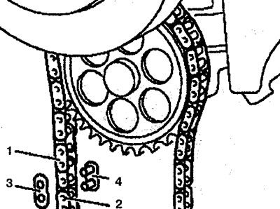
Figure 2.85. Attach the new chain to the old one.
4. Rotate the crankshaft slowly in the direction of rotation until it is possible to disconnect the old chain and connect both ends of the new chain.
5. Disconnect the old chain 1 and connect the ends of the new chain 2 using a new intermediate link 4 (see figure 2.86).
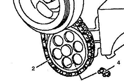
Figure 2.86. Connect the ends of the new chain 2 using a new intermediate link 4.
6. Install the compression element 2 in a vice (arrow) and secure it with screw 5 (see figure 2.87).
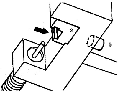
Figure 2.87. Install the compression element 2 in a vice (arrow) and secure it with screw 5.
7. Install the clamping element 2 (arrow) in a vice (see figure 2.88).
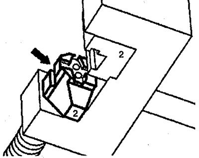
Figure 2.88. Install the compression element 2 (arrow) in a vice.
8. Install the new outer plate (arrow) in a vice (see figure 2.89).
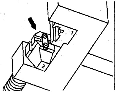
Figure 2.89. Install the new outer plate (arrow) in a vice.
9. Tighten spindle 6 until it stops (see figure 2.90). When tightening spindle 6, make sure that the intermediate link pins are inserted into the holes of the outer plate 3 of the link.
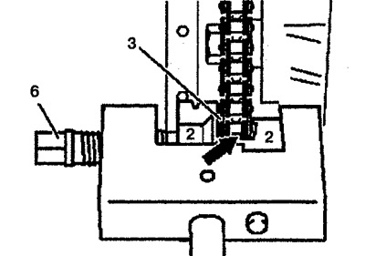
Figure 2.90. Tighten spindle 6 until it stops.
10. Remove the compression element 2 and reinstall it, placing it on the riveted profile (arrow) (see figure 2.91).
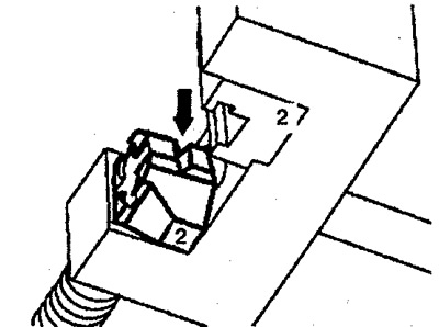
Figure 2.91. Remove compression element 2 and reinstall it (arrow).
11. Install the compression element in the center of the bolt (arrow) (see figure 2.92).
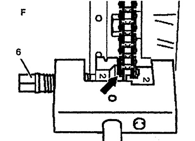
Figure 2.92. Install the compression element in the center of the bolt (arrow).
12. Tighten spindle 6 to 30-35 Nm. Rivet the intermediate link pins individually.
13. Check the riveting of the chain link and re-rivet if necessary (see figure 2.93).
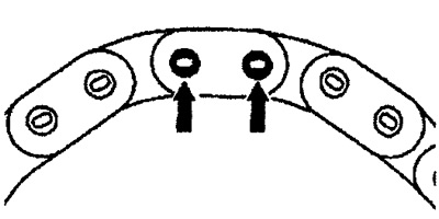
Figure 2.93. Check the riveting of the chain link.