
Removing
1. On 111 engines: secure tensioner rocker arm 2 and idler pulley 3 against movement in the direction of rotation (see fig. 1.8).
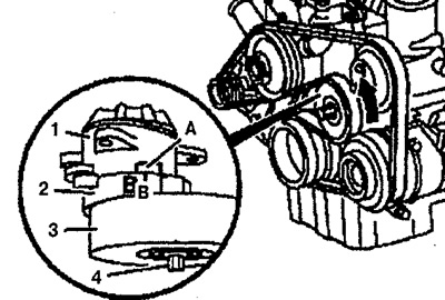
Pic. 1.8. Loosening of the drive belt on engines 111.979.
2. Remove the alternator drive belt.
Examination
3. Check the condition of the pulleys and belt tensioner for damage and contamination. Replace damaged elements if necessary.
Installation
4. Install the drive belt on the pulleys, starting with the tensioner pulley (see fig. 1.9 a, b, 1.10a, b, 1.11).
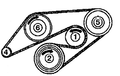
Pic. 1.9a. Alternator drive belt installation diagram on engine 111 (without air conditioning).
Pic. 1.9b. Alternator drive belt installation diagram on engine 111 (air conditioned).
1. Idler pulley,
2. Crankshaft pulley,
3. Air conditioner compressor,
4. Generator,
5. Power steering pump,
6. Water pump.
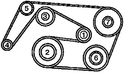
Pic. 1.10a. Alternator drive belt installation diagram on engine 611.980 (without air conditioning).
1. Idler pulley,
2. Crankshaft pulley,
4. Generator,
5. Power steering pump,
6. Water pump,
7. Guide pulley.
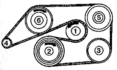
Pic. 1.10b. Alternator drive belt installation diagram on engine 611.980 (air conditioned).
1. Idler pulley,
2. Crankshaft pulley,
3. Air conditioner compressor,
4. Generator,
5. Power steering pump,
6. Water pump.
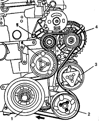
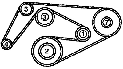
Pic. 1.11. Alternator drive belt installation diagram on engine 104.900:
1. Crankshaft pulley,
2. Power steering pump, 3. A/C compressor, 4. Alternator, 5. Idler pulley, 6. Water pump.
5. Tension the drive belt.
On engines 111.979:
- secure the tensioner oscillating arm 2 and the tensioning pulley 3 against movement in the direction of rotation (see fig. 1.8). Install the belt on the water pump pulley;
- release the rocker arm and idler pulley. Check the installation of the belt and the location of marks B on the tension lever and the indication surface of the housing A. If the belt is selected and installed correctly, the mark B should be one third of the indication surface to the left (see fig. 1.8).