
Adjustment of a convergence of forward wheels
Front wheel toe-in is defined as the difference in the distances between the inner edges of the wheel rims, measured on the front and rear sides at the height of the wheel hub axle.
Increased toe-in leads to wear on the outer side of the tires. insufficient toe-in leads to wear on the inside of the tires. For an accurate check, it is necessary to install an extension on the front side of both wheels. This compensates for the change in toe-in during movement due to the elasticity of the steering rods. We assume that there is no stretching available, the work can be done without it, however, in this case, we advise you to additionally check the convergence at a service station. Front wheel alignment is checked in the following sequence:
Set the steering to the middle position for driving in the forward direction. To do this, turn the steering wheel until the clamping bolt on the shaft is in a horizontal position, which corresponds to the horizontal position of the lining on the steering wheel. Mercedes-Benz Service Stations use a special bolt to adjust the center position, which is not described in this manual.
Measure the distance between the edges of the front wheel rims on the front side at the height of the hub axle and mark the measuring points with chalk.
Roll the car over half a turn of the wheel and measure the distance between the edges of the discs on the rear side at the height of the hub axle in the places marked with chalk. Compare measurement results. When measuring without using the wheel brace, the toe-in value should be 5 mm±1 mm, with the wheel brace being used, the toe-in should be 2.5 mm±1 mm.
If necessary, toe-in adjustment is carried out by simultaneously changing the length of the steering rods. From the outside, the tie rod ball end is fastened with a conical ring and a lock nut: from the inside, with a clamp with a bolt and nut. After loosening the fastening, the thrust pipe is rotated in the required direction simultaneously from the left and right sides, the steering wheel should be in the middle position.
Measure the toe after adjustment as described above and tighten the fasteners on the tie rods. Tighten the clamp mounting on the inside of the tie rod, then hold the tapered ring from turning and tighten the lock nut. Before the final tightening of the fasteners, check that the ball joints of the tips are in the middle position to avoid damage during movement.
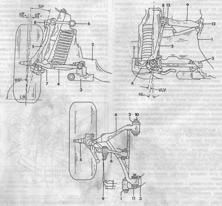
Pic. 220. Adjusting the angles of the front wheels.
1 - longitudinal reinforcement of the body,
2 - body cross member,
3 - traverse,
4 - lower transverse suspension arm,
5 - pivot pin,
6 - upper transverse suspension arm,
7 - lower ball joint,
8 - upper ball joint,
9 - anti-roll bar,
10 - eccentric bolt (camber adjustment),
11 - eccentric bolt (adjustment of the longitudinal angle of inclination of the axis of rotation),
12 - anti-roll bar support on the upper transverse suspension arm,
ST - collapse,
NL - longitudinal angle of inclination of the axis of rotation,
SP - longitudinal angle of inclination of the axis of rotation,
LR - wheel rolling radius,
VLV - displacement of the wheel axis from the axis of rotation.