
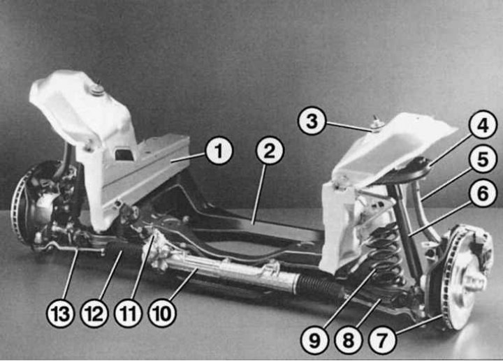
Pic. 7.1. Front suspension: 1 – body spar; 2 - bearing beam; 3 – shock absorber cup; 4 - upper transverse lever; 5 – rotary fist; 6 - shock absorber; 7 - brake disc with caliper; 8 - lower transverse lever; 9 - twisted spring; 10 – the case of a rack and pinion of a steering; 11 - steering shaft with gear; 12 – a dirt-protective cover of steering draft; 13 - left tie rod
The design of the front suspension of a Mercedes E-class car is shown in fig. 7.1. The use of a modern double wishbone design has improved comfort, steering function of the suspension and steering of the car. Each front wheel has an independent suspension to the body.
Front suspension double wishbone. A similar scheme replaced the shock absorber strut on the previous model. It is also used on S- and C-class models. With this scheme, the shock absorber and spring are installed separately. Thanks to the double arms, the shock absorbers are freed from the function of guiding the front wheels, which allows them to better perform their main task - vibration damping.
Wishbones
The direction of each front wheel is carried out by two (top and bottom) triangular wishbones. Upper arm 4 (see fig. 7.1) connected directly to the body through a large rubber-metal joint, and the lower arm is fixed to the carrier beam 2 of the front suspension.
Lower ball joint
The coil spring 9 and the shock absorber 6 rest on the body through the so-called lower ball joint, which has a variable spring characteristic, and become more rigid as the damping force increases.
Shock absorber
The separate location of the shock absorber determines the precise behavior of the wheel when working out road bumps. The result of the separate position of the spring and shock absorber is clearly visible in practice. For example, when driving in a straight line or side wind. The Mercedes E-Class does not deviate for every rut on the road and only slightly deviates from the course in a sudden gust of wind.
Computer-calculated double wishbone front suspension rubber elements (Latin designation DQ) allow changing the directions of the wheels only within certain limits and thereby significantly improve the stability of the vehicle when braking and cornering. Thus, during depreciation, the camber and toe-in angles do not change significantly, which has a positive effect on the rolling resistance characteristic and tire wear. The suspension geometry, combined with the elasto-kinematics of the double wishbone system, guarantees a neutral or easily adjustable vehicle steering, which is an indispensable principle of Mercedes-Benz chassis design for active safety.
Stretcher
Unlike other Mercedes passenger car models, the lower wishbones and steering gear of the E-Class are mounted on the front suspension carrier beam, which is shaped like a frame. This so-called subframe, in turn, is bolted to the front side members of the body and facilitates the installation of the engine and front suspension when assembling the car. In addition, it increases the protection of passengers in a frontal impact and serves to separate the chassis from the body. Thus, thanks to the subframe, vibrations and noises during movement are less transmitted to the passenger compartment. Engine mounts and steering are mounted on the subframe itself.
Rack and pinion steering
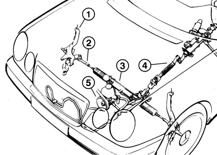
Pic. 7.2. Steering: 1 – a rotary fist; 2 – right steering draft; 3 - gear rack housing; 4 - steering shaft (in two parts); 5 - hydraulic booster pump
A novelty in the design is the installation of the lower wishbones in the forward direction. In addition, another upgrade was made - power rack and pinion steering replaced the previous type steering scheme «screw nut», which no longer corresponded to the promising concept of Mercedes-Benz to lighten the design. New steering design (pic. 7.2) now there are no bipods, intermediate levers, stiffening plates and fasteners. Steering rods are connected to the steering mechanism without intermediate bypass elements. The design thus ensures correct and precise handling.
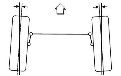
Pic. 7.3. Schematic representation of wheel alignment
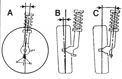
Pic. 7.4. Wheel alignment angles: A - angle of longitudinal inclination; B - camber angle; C - the angle of the transverse slope
Suspension Geometry Terms
wheel alignment. The steerable wheels are more closely spaced at the front than at the rear (have a sort of counter-rolling) (pic. 7.3). This evens out the frictional force between the road surface and the wheel, which tends to point the left wheel to the left and the right wheel to the right. Toe-in prevents wheel vibration and one-sided tire wear. When cornering, the wheel on the inside radius is fed more in the direction of the turn to support the turning movement and is more stressed by the turning force than the wheel on the outside radius, so the toe angle is reversed (rear wheels are brought closer to each other).
collapse. Determines the inclination of the front wheels in the vertical plane (pic. 7.4, B). The camber reduces the impact of road bumps on the steering, reduces the force on the steering wheel and the friction force of the wheels on the roadway.
The angle of the transverse inclination of the axis of rotation of the wheel. The angle between the axis of rotation of the wheel and the vertical (see fig. 7.4, C). If we continue the line of this axis to the ground and determine the distance from it to the central point of contact of the wheel with the road, then we get the running shoulder. It should be as small as possible in order to reduce the influence of side forces on the control. The lateral tilt angle together with the longitudinal tilt angle have the effect that when the wheels are turned, the car rises slightly, and when the steering wheel is released, the front wheels themselves return to the middle position.
The angle of the longitudinal inclination of the axis of rotation of the wheel. The angle between the axis of rotation of the wheel when viewed from the side and the vertical (pic. 7.4, A). Due to the caster angle in relation to the front wheels, a pulling force is applied rather than a pushing force. That is why the wheels tend to maintain a straight line.
New steering
The new steering design no longer has bipods, intermediate levers, stiffening plates and fasteners. Steering rods are connected to the steering mechanism without intermediate bypass elements. This not only facilitates installation, but also reduces weight. The design provides correct and precise handling. By attaching the steering to the subframe through elastic elements, the transmission of road irregularities to the steering wheel is significantly reduced, so that the new design, among other advantages, also increases comfort. Since the steering mechanism is located rather in the inner part of the subframe, Mercedes engineers have developed a steering shaft with two cross joints. They even out some axial displacement between the steering mechanism and the steering shaft, and also serve to reduce vibrations, which are damped by a torsional vibration damper built into the first joint. The second cross joint is an oscillating joint, which allows for individual adjustment of the position of the steering column in length and height, which is also equipped with an electric drive.