



Contents: Removal ↡ Installation ↡
The power that an engine can develop depends on the amount of air and fuel that enters the engine cylinders. To increase engine power, both the amount of air and fuel supplied must be increased. Supplying more fuel will not have an effect until there is enough air to burn it, otherwise there will be an excess of unburned fuel, which will cause the engine to overheat and also smoke heavily. To increase the amount of air supplied to the engine, a turbocharger is used, which compresses the air supplied to the combustion chamber.
The turbocharger consists of a centrifugal air pump and a turbine connected by a common rigid axis. Both of these elements rotate in the same direction and at the same speed. The energy of the exhaust gas flow, which is not used in conventional engines, is converted here into torque, which drives the turbocharger. The exhaust gases leaving the engine cylinders have a high temperature and pressure. They are accelerated to a high speed and come into contact with the turbine blades, which converts their kinetic energy into mechanical rotational energy. This energy conversion is accompanied by a decrease in the temperature of the exhaust gases and their pressure. The turbocharger sucks in air through the air filter, compresses it and feeds it into the engine cylinders. The amount of fuel that can be mixed with air can be increased, which allows the engine to develop more power.
The turbocharger is installed under the exhaust manifold. To lubricate the turbocharger, engine oil is supplied under pressure through a special pipeline from the cylinder head. The turbocharger has a relief valve and a vacuum diaphragm, which serves to limit the pressure supplied by the turbocharger to the intake manifold.
Since the turbocharger operates at high speeds, care and cleanliness must be taken to ensure that no contaminants enter the turbocharger and cause it to fail.
Caution! Before disconnecting any components from the turbocharger, thoroughly clean them. To protect against contamination, place the components removed from the turbocharger in a sealed container. To prevent contamination from entering the turbocharger, close the air ducts of the turbocharger.
Removal
Turbocharger
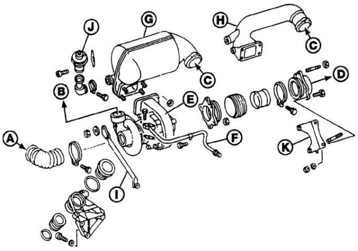
A – from the air filter; B – to the intake manifold; C – from the exhaust manifold; D – to the exhaust inlet pipe; E – turbocharger; F – oil supply pipe; G – oxidizer; H – exhaust gas supply pipe; I – emphasis; J – EGR valve; K – bracket
1. Remove the ground cable from the battery.
2. Release the clips and remove the splash shield from the lower part of the engine compartment.
3. Remove the air filter. On models with an oxidizer, unscrew the screws and remove the heat shield installed between the air filter and the oxidizer.
4. Loosen the clamps and remove the air duct connecting the turbo generator to the air filter (see picture).
5. Label and disconnect the vacuum hoses from the diaphragm housing and EGR valve.
6. If equipped, loosen the clamps and remove the corrugated hose from the base of the EGR valve.
7. Unscrew the nuts and remove the oxidizer together with the bracket from the exhaust manifold.
Attention! On cars without an oxidizer, an exhaust gas supply pipe is installed to the turbocharger.
8. Loosen the clamps and remove the air ducts connecting the turbocharger to the intake manifold.
9. Loosen the clamps and remove the mixing tube located at the base of the EGR valve from the turbocharger.
10. Unscrew the union nuts and disconnect the oil supply and return pipes from the turbocharger. Remove the sealing gaskets. Remove the oil supply pipe from the mounting bracket on the intake manifold.
11. Unscrew the nuts and separate the exhaust inlet pipe from the turbocharger. Remove the gasket.
Text republished from the website MercedesMAN.ru
12. Remove the bolts and remove the turbocharger from the bracket.
Installation
1. Installation is carried out in the reverse order of removal, taking into account the following points.
2. Before tightening the turbocharger to bracket bolts, tighten the exhaust pipe to turbocharger mounting nuts.
3. Apply a thin coat of high temperature grease to the threads and heads of the new oxidizer connecting pipe mounting bolts, then install the bolts and tighten them to the specified torque.
4. Using clean engine oil, flush the oil feed pipe to the turbocharger and the oil inlet port of the turbocharger. Install the oil pickup pipe and tighten the union nuts to the specified torque.
5. Connect the vacuum hoses according to the previously made markings.
6. Start the engine at idle speed and let it run at this speed for at least 1 minute to allow oil to flow to the turbocharger bearings.