
Air filter replacement
See subsection 11.4.
Fuel filter replacement
See subsection 10.6.
Changing the oil and filter in an automatic transmission
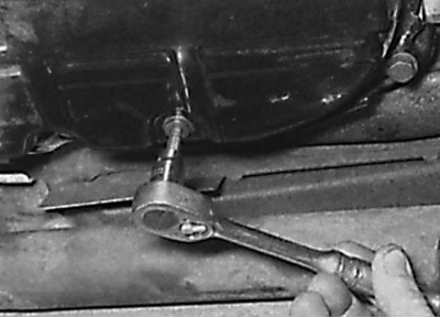
Unscrewing the oil drain plug from the automatic transmission
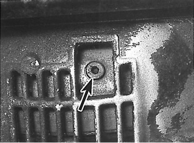
Location of the oil drain plug from the torque converter
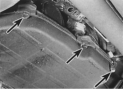
Arrangement of bolts of fastening of the pallet of an automatic transmission
Removing the strainer
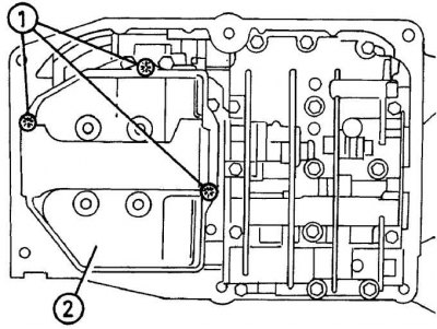
After loosening the clamping screws (1) remove the strainer (2).
1. Raise the car on a lift.
2. To access the gearbox, remove the lower mudguard.
3. Set the selector lever to position P.
4. Thoroughly wipe down the automatic transmission pan.
5. Place a suitable container under the gearbox drain plug, then unscrew the drain plug and after the oil drains, screw the drain plug back into place (see fig. Unscrewing the oil drain plug from the automatic transmission).
6. At the crankshaft pulley bolt, rotate the engine crankshaft until the torque converter drain plug is visible through the hole in the gearbox housing (see fig. Location of the oil drain plug from the torque converter).
7. Place a suitable container under the torque converter drain plug and unscrew the drain plug. After completely draining the fluid from the torque converter, reinstall the drain plug.
8. Unscrew the pan mounting bolts, then remove the clamping strips and lower the pan away from the gearbox (see fig. Arrangement of bolts of fastening of the pallet of an automatic transmission). Remove the rubber pad.
9. Unscrew the screws and remove the strainer (see fig. Removing the strainer).
10. Clean the inside surface of the automatic transmission pan.
11. Install new strainer and secure with screws.
12. Install the pallet and clamping strips and secure the pallet with bolts, tightening them to the required torque.
13. If available, install a mudguard.
14. Lower the vehicle to the ground, then release the lock lever and remove the automatic transmission oil dipstick.
15. Pour 4 liters of the required fluid into the gearbox through the dipstick tube. Start the engine at idle with the selector lever in position P.
16. Continue adding fluid gradually until the level is 12mm below the min mark on the dipstick.
17. Move the selector lever to all positions, holding it in each position for a few seconds, then return the selector lever to position P.
18. Recheck the fluid level in the automatic transmission.
19. Refill fluid to a level of 12 mm below the min mark and move the selector lever to all positions, then set to position P. Repeat this operation until the fluid level in the gearbox remains constant.
20. Take a short drive and recheck the fluid level in the automatic transmission.
Checking the wear of the clutch disc linings
Clutch lining wear template
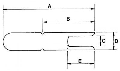
A = 55 mm;
H = 26 mm;
C = 7 mm;
D = 14 mm;
E = 12 mm
Using a Gauge to Check Clutch Lining Wear
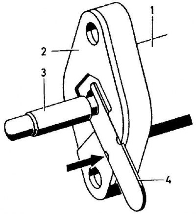
1 - clutch slave cylinder;
2 - gasket;
3 - pusher;
4 - template
The arrows show two marks on the template.
In this position of the template, the clutch disc linings are in satisfactory condition.
Using a Gauge to Check Clutch Lining Wear
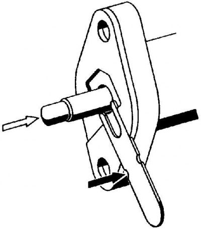
This position of the template indicates that the clutch disc linings have reached their wear limit.
Light arrow - the pusher moves in the presence of wear.
The dark arrow is a mark on the template.
1. Checking the wear of the clutch disc lining is carried out without removing the clutch disc from the vehicle.
2. The test can be performed from the underside of the clutch slave cylinder and requires the use of a special template, which can be made from a strip of metal (see fig. Clutch lining wear template).
3. Raise the front of the car and secure it on stands.
4. Insert the template into the groove between the protrusion of the clutch slave cylinder and the crankcase.
5. Move the template all the way until the end of the template comes into contact with the pushrod of the clutch slave cylinder.
6. If the two marks on the template are not visible, then the clutch disc linings are in satisfactory condition. If two marks on the template are visible, the clutch disc lining has reached its wear limit and the clutch disc must be replaced (see fig. Using a Clutch Pad Wear Gauge Using a Clutch Pad Wear Gauge).
7. Remove template and lower vehicle.