
Replacing spark plugs
Proper functioning of spark plugs is one of the most important conditions for the efficient operation of the engine. It is essential that only the specified type of spark plugs be fitted to the engine. With a good engine, cleaning spark plugs is a rare operation.
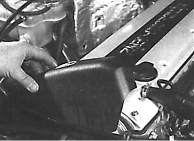
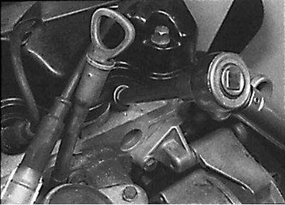
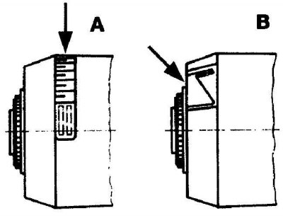
Removing the front cover on a DOHC engine with KE-JETRONIC injection
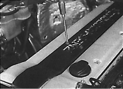
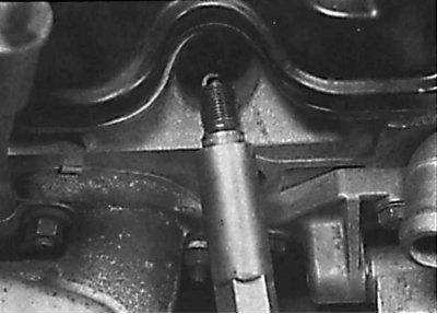
Unscrewing the screws securing the cover that closes the spark plugs
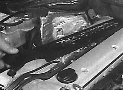
Removing the spark plug cover
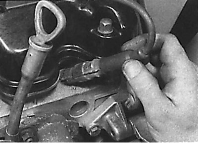
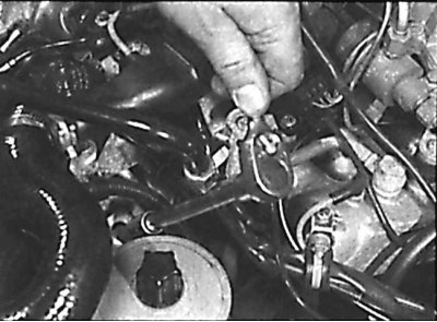
Removing the high voltage wire from the spark plugs on a 6-cylinder DOHC engine
Removing the high voltage wire from the spark plug on a 4-cylinder engine
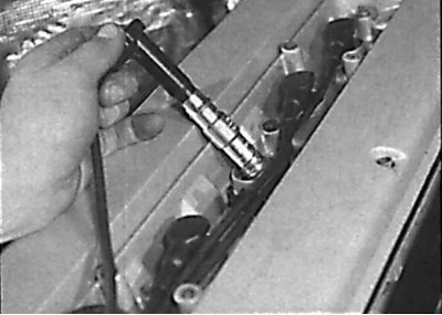
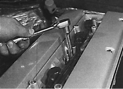
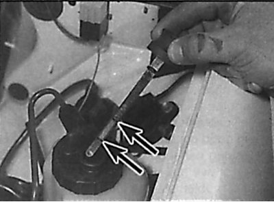
Removing a spark plug from a 6-cylinder DOHC engine
Removing a spark plug from a 4-cylinder engine
Removing the spark plug from a 4-cylinder engine
Measuring spark plug gap using a feeler blade
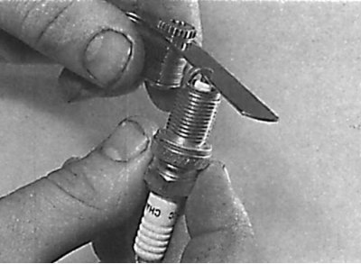
Using a special tool to bend the ground electrode of the spark plug
Screwing the spark plug into the engine
1. On DOHC engines with KE-JETRONIC injection, remove the front cover, unscrew the screws and remove the spark plug cover (see fig. Removing the front cover on a DOHC engine with a KE-JETRONIC injection system, Unscrewing the screws securing the spark plug cover, Removing the spark plug cover).
2. On DOHC engines with HFM engine management, remove the ignition coils from the top cylinder head cover.
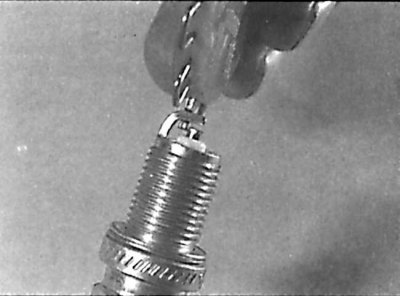
3. Remove the high voltage wires from the spark plugs by pulling on the spark plug tip (see fig. Removing the high voltage wire from the spark plugs on a 6-cylinder DOHC engine, Removing the high voltage wire from the spark plug on a 4-cylinder engine).
4. Clean the spark plugs using a brush, vacuum cleaner or compressed air to prevent dirt from entering the engine cylinders after the spark plugs are removed.
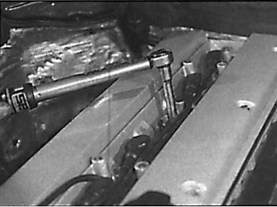
5. Using a spark plug wrench, unscrew the spark plugs (see fig. Removing a spark plug from a 6-cylinder DOHC engine, Removing a spark plug from a 4-cylinder engine, Removing a spark plug from a 4-cylinder engine).
6. Visual inspection of the working part of the spark plugs can show the condition of the engine. If the nose of the spark plug insulator is clean and white with no deposits, then the mixture is too lean. It also indicates that the spark plug is too hot, i.e. heat is slowly removed from the center electrode. If this is the case, then you need to adjust the composition of the mixture or replace the candle.
7. If the nose of the candle insulator is covered with a black coating, then this indicates that the mixture is too rich. If the plaque is black and oily, then this indicates engine wear and the need to check and repair it. If the nose of the insulator is covered with a light brown coating, then the mixture is optimal and the engine is in good condition.
8. The gap between the electrodes of a spark plug is of great importance, because if the gap is too large or too small, the size of the spark changes, which leads to a decrease in the efficiency of the engine. The gap must always comply with the technical requirements.
9. Checking the gap is carried out with a wire gauge or feeler gauge. The gap is adjusted by bending the side electrode. In no case should the central electrode be bent, as this can lead to breakage of the insulator and failure of the candle (see fig. Measuring spark plug gap using a feeler blade).
10. To bend the side electrode of the spark plug, you must use a special tool (see fig. Using a special tool to bend the ground electrode of the spark plug).
11. Before installing the spark plug in the engine, check that the threads are clean and that all threads are intact.
12. To screw the spark plug several turns, you can use a piece of rubber hose, into which, on one side, insert the spark plug insulator and, turning the hose, screw the spark plug several turns. Then you need to remove the hose and screw the candle to the required torque (see fig. Screwing the spark plug into the engine).
13. Connect high-voltage wires to spark plugs and install all previously removed elements.
Checking the elements of the self-levelling rear suspension system
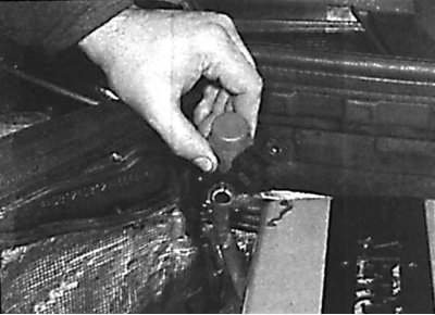
Removing the dipstick from the tank of the self-levelling rear suspension system
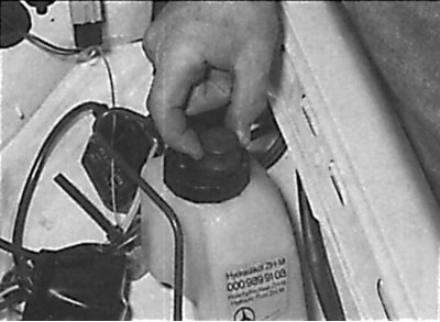
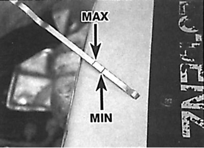
Fluid level in self-leveling rear suspension system
The fluid level in the self-levelling rear suspension system must be between the MIN and MAX marks on the dipstick.
Below is the procedure for performing work on models with a station wagon body.
1. Park the vehicle on a level surface and open the hood. Check the fluid level in the self leveling rear suspension system with the vehicle unloaded.
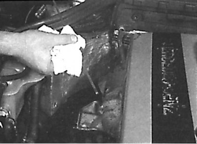
2. Remove the dipstick and use a clean rag to wipe the liquid off the dipstick. Insert a clean dipstick into the tank and remove it again. Check the fluid level, which should be between the MAX and MIN·marks on the dipstick (see fig. Removing the dipstick from the tank of the self-levelling rear suspension system, Fluid level in the self-levelling rear suspension system). If the fluid level is checked with a loaded vehicle, the fluid level may be below the MIN·mark.
3. If necessary, add the required amount of the specified fluid through the dipstick hole.
Checking the oil level in an automatic transmission
Check the oil level in the automatic transmission when the transmission is warm (oil temperature 80°C).
Removing the dipstick for measuring the oil level in an automatic transmission
Using a rag to clean the oil dipstick in an automatic transmission
The location of the marks on the dipstick for measuring the oil level in an automatic transmission
1. Park the vehicle on a level, level ground.
2. Start the engine at idle speed and set the selector lever to position P and apply the handbrake.
3. Release the lock lever, remove the dipstick from the gearbox, wipe it clean and reinstall it (see fig. Removing the dipstick for measuring the oil level in an automatic transmission, Using a rag to wipe the dipstick for measuring the oil level in an automatic transmission).
4. Remove the dipstick and check that the oil level is between the MIN and MAX marks (see fig. The location of the marks on the dipstick for measuring the oil level in an automatic transmission).
5. If the oil level is below the MIN·mark, add oil through the dipstick hole.
6. If there is a need to add oil frequently, then it means that there is a leak that must be found and repaired as long as it does not lead to serious consequences.
Checking the tightness of the hoses and fluid leakage
Leaks in the cooling system are usually detected by a white or rust-colored coating in the area adjacent to the leak.
1. Carefully check the radiator and coolant hoses along the entire length. Replace hoses with cracks, tears or signs of ageing. Cracks are easier to find if the hose is pinched. Pay special attention to the clamps that attach the hoses to the elements of the cooling system. Hose clamps that have been overtightened can cause the hose to break or puncture, resulting in leaks in the cooling system. Inspect all hoses and hose connection surfaces for leaks. If any problems of this nature are found with leaks, then replace this component or gasket.
2. Fuel leaks are difficult to pinpoint until the leak is significant and therefore easily visible. Fuel tends to evaporate quickly as soon as it comes into contact with air, especially in a hot engine bay. Small drops may disappear before you can locate the leak. If you suspect that there is a fuel leak in the area of the engine compartment, then cool the engine and start it while it is cold with the hood open. Metal objects tend to shrink when cold, and rubber hoses tend to loosen up, so any leaks will be more obvious as the engine warms up from a cold start.
3. If there are indications that some fluid is leaking, but you cannot recognize the type of fluid or the exact origin, then you should leave the car for a long time and put a large piece of paper or rag under the car. This will help locate the fluid leak and also help identify the leaking fluid by color. But keep in mind that some leaks may only show up when the engine is running.
4. A leak in the vacuum hose means that air is being sucked into the hose (does not come out of the hose), and this makes the leak very difficult to detect. The detection method is to use an old vacuum hose as a kind of stethoscope. Hold one end of the hose close to your ear (but not in the ear), and use the other end to examine the area around the suspected leak. When the end of the hose is directly over the leak, a hissing sound will be clearly audible through the hose. Contact with hot and moving parts must be avoided, as the engine must be running during the test.
Checking and replacing the auxiliary drive belt
1. With the engine off, inspect the condition of the auxiliary drive belt along its entire length. Check the accessory belt pulleys for nicks, cracks, deformation, and corrosion.
Replacing the auxiliary drive belt on a four-cylinder engine
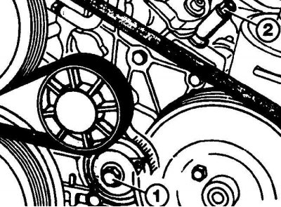
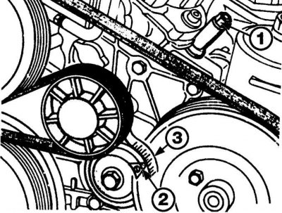
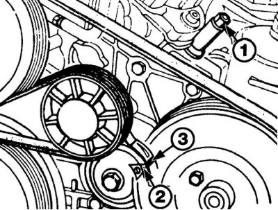
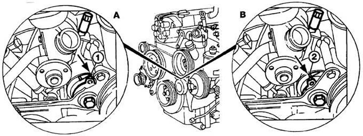
Bolt location of the auxiliary drive belt tensioner (1) and regulator nuts (2) on 4-cylinder engines
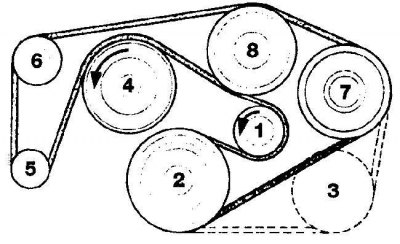
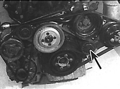
Location of the auxiliary drive belt on a 4-cylinder engine without power steering
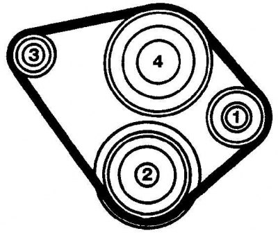
The sequence of installing the drive belt on the pulleys:
1 - pulley of the tension mechanism; 2 - crankshaft pulley; 3 - generator pulley; 4 - water pump
Location of the auxiliary drive belt on a 4-cylinder engine with power steering, but without an air conditioning system
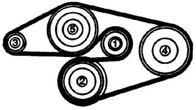
The sequence of installing the drive belt on the pulleys:
1 - pulley of the tension mechanism; 2 - crankshaft pulley; 3 - generator pulley; 4 – a pulley of the pump of the amplifier of a steering; 5 - water pump pulley
Location of the auxiliary drive belt on a 4-cylinder engine with power steering and air conditioning
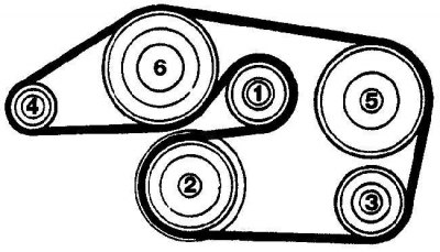
The sequence of installing the drive belt on the pulleys:
1 - pulley of the tension mechanism; 2 - crankshaft pulley; 3 - a pulley of the air conditioning compressor; 4 - generator pulley; 5 – a pulley of the pump of the amplifier of a steering; 6 - water pump pulley
1. Remove the radiator fan impeller and shroud.
2. Loosen the auxiliary belt tensioner bolt a quarter of a turn (see fig. Bolt location of the auxiliary drive belt tensioner (1) and regulator nuts (2) on 4-cylinder engines).
3. Turning counterclockwise loosen the adjuster nut and unscrew the adjuster until the auxiliary drive belt is completely loosened. Remove the auxiliary drive belt from the pulleys.
4. Install the new drive belt on the pulleys, starting with the tensioner pulley and proceeding in the sequence shown in the figures Location of the auxiliary drive belt on a 4-cylinder engine without power steering, Location of the auxiliary drive belt on a 4-cylinder engine with power steering, but without air conditioning, Location of the auxiliary drive belt on a 4-cylinder engine with power steering and air conditioning.
5. Adjust the tension of the auxiliary drive belt as follows.
Models with a scale bar on the tension mechanism
Adjusting the tension of the auxiliary belt on 4-cylinder engines
To adjust the tension of the auxiliary belt on 4-cylinder engines, turn the adjuster nut (1) before pointer alignment (2) with the fifth mark on the scale bar (3).
1. On vehicles without power steering, turn the adjuster nut clockwise until the tensioner pointer aligns with the fifth notch from the left on the scale (see fig. Adjusting the tension of the auxiliary belt on 4-cylinder engines).
2. On power steering models, turn the adjuster nut clockwise until the tensioner pointer is between the 8th and 9th marks on the left of the scale bar.
3. Tighten the tensioner mounting bolt to the required torque.
4. Install the fan impeller and shroud.
Models with a single thick mark
Adjusting the tension of the auxiliary belt on a 4-cylinder engine
To adjust the tension of the auxiliary drive belt on a 4-cylinder engine, turn the adjuster nut (1) while pointer (2) not compatible with thick line (3).
1. Rotating the adjuster nut clockwise, align the tensioner pointer with the thick mark (see fig. Adjusting the tension of the auxiliary belt on a 4-cylinder engine).
2. Tighten the tensioner mounting bolt to the required torque.
3. Install the fan impeller and shroud.
Replacing the auxiliary belt on 6-cylinder SOHC engines
Tensioner mounting bolt location (1) and regulator nuts (2) on 6-cylinder SOHC engines
Auxiliary drive belt location on 6-cylinder SOHC engine without air fuel pump
Auxiliary Drive Belt Location on 6-Cylinder SOHC Engines with Air Fuel Pump

1. Remove the radiator fan impeller and shroud.
2. Loosen the tensioner mounting bolt 1/2 turn (see fig. Tensioner mounting bolt location (1) and regulator nuts (2) on 6-cylinder SOHC engines).
3. Turn the adjuster nut counterclockwise to unscrew the adjuster to free the auxiliary drive belt. Remove the auxiliary drive belt from the pulleys.
4. Install the new auxiliary drive belt onto the pulleys, starting with the idler pulley and moving forward in the sequence shown in the figures Location of the auxiliary drive belt on 6-cylinder SOHC engines without air fuel pump, Location of the auxiliary drive belt on 6-cylinder SOHC engines with air fuel pump.
5. Adjust the tension of the auxiliary drive belt as follows.
Models with a scale bar on the regulator
6-cylinder SOHC auxiliary drive belt tensioners
A - regulator with a scale bar;
B - regulator with triangular pointer
1. Move the tensioner pointer to align with the right end of the scale bar as viewed from the front of the engine compartment (see fig. 6-cylinder SOHC auxiliary drive belt tensioners).
2. On models without air conditioning, turn the adjuster nut clockwise until the tensioner pointer aligns with the fifth notch on the scale bar.
3. On models with air conditioning, turn the adjuster nut clockwise until the tensioner pointer aligns with the seventh mark on the scale bar.
4. Tighten the tensioner mounting bolt to the required torque.
5. Install the fan impeller and shroud.
Models with a single thick notch in the tensioner
Auxiliary drive belt tension adjuster on 6-cylinder SOHC engine
A - when combining the pointer of the tension mechanism (1) with the right end of the arrow on the scale bar, the slack of the auxiliary drive belt is removed; B - when the index of the tension mechanism is combined (2) with a thick line on the scale bar, the required toothed belt tension is produced.
1. Move the tensioner pointer so that the tip of the pointer aligns with the narrowest right end of the triangle.
2. Turn the adjuster nut clockwise until the tip of the tensioner pointer aligns with the thick line (see fig. Auxiliary drive belt tension adjuster on 6-cylinder SOHC engine).
3. Tighten the tensioner mounting bolt to the required torque.
4. Install the radiator fan impeller and shroud.
Auxiliary belt replacement on 6-cylinder DOHC engines
Models with Tension Adjuster Pointer
Location of the plastic cover
The arrow indicates the one that must be removed to access the DOHC 6-cylinder tensioner bolt with tensioner indicator.
Loosening the drive belt tensioner mounting bolt on a 6-cylinder DOHC engine with a tensioner indicator
Unscrewing the nut of the auxiliary drive belt adjuster on a 6-cylinder DOHC engine
Auxiliary drive belt location on 6-cylinder DOHC engine
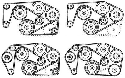
The sequence of installing the auxiliary drive belt on the pulleys:
1 - pulley of the tension mechanism; 2 - crankshaft pulley; 3 – a pulley of the compressor of an air conditioning system; 4 - idle pulley; 5 - radiator fan pulley; 6 – a pulley of the air fuel pump; 7 - generator pulley; 8 - idle pulley; 9 – a pulley of the pump of the amplifier of a steering; 10 - water pump pulley
1. Remove the radiator fan impeller and shroud.
2. Loosen the tensioner bolt a quarter of a turn (see fig. Plastic Cover Location, Drive Belt Tensioner Bolt Loose on 6-Cylinder DOHC Engine with Tensioner Pointer).
3. Unscrew the adjuster nut counterclockwise and unscrew the adjuster until the belt is completely loosened. Remove the belt from the pulleys (see fig. Unscrewing the nut of the auxiliary drive belt adjuster on a 6-cylinder DOHC engine).
4. Install the new auxiliary drive belt onto the pulleys, starting with the idler pulley and in the sequence shown in Figure Location of the auxiliary drive belt on a 6-cylinder DOHC engine.
5. Adjust the tension of the auxiliary drive belt as follows.
6. Move the tensioner pointer until the tip of the pointer aligns with the right narrowest end of the triangle on the scale bar.
7. Turn the adjuster nut clockwise until the tip of the tensioner pointer aligns with the thick line on the scale bar (see fig. Auxiliary drive belt tension adjuster on 6-cylinder SOHC engine).
8. Tighten the tensioner mounting bolt to the required torque.
9. Install the radiator fan impeller and shroud.
Models with automatic regulator
Reducing tension on the auxiliary drive belt
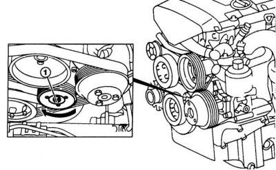
To reduce tension on the auxiliary drive belt on 6-cylinder DOHC engines, install a wrench on the tensioner pulley nut (1) and turn the wrench clockwise.
1. Remove the radiator fan impeller and shroud.
2. Place a wrench in the center of the tensioner pulley and use the wrench to turn the tensioner clockwise to reduce the tension on the auxiliary drive belt (see fig. Reducing tension on the auxiliary drive belt).
3. Secure the tensioner in this position with a wrench and remove the auxiliary drive belt from the pulleys.
4. Install the new auxiliary drive belt onto the pulleys, starting with the idler pulley and continuing in the sequence shown in Figure Location of the auxiliary drive belt on a 6-cylinder DOHC engine.
5. Release the wrench holding the tensioner, which will cause the tensioner to rotate and tension the auxiliary drive belt.
6. Install the fan impeller and shroud.
Checking the air conditioning system
The location of the viewing window for checking the fluid level in the air conditioning system
1. The air conditioning pressure sensor is located on the side of the nutrient tank.
2. Switch off the ignition and disconnect the electrical connector from the top of the pressure sensor.
3. Start the engine at idle and turn on the air conditioning system on the instrument panel.
4. Wipe the viewing window located on the side of the nutrient tank (see picture).
5. Connect the electrical connector to the pressure sensor and observe the viewing window. As a result of this, the electromagnetic clutch will turn on and the refrigerant level in the viewing window should rise. The refrigerant visible in the sight glass must be free of air bubbles.
If the refrigerant level in the air conditioning system is too low or the pressure in the system is too low, the pressure sensor will prevent the air conditioning system from turning on. In this case, the air conditioning system must be repaired by a specialist workshop.
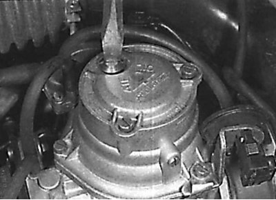
Checking the oil level in the piston shock absorber (STROMBERG)
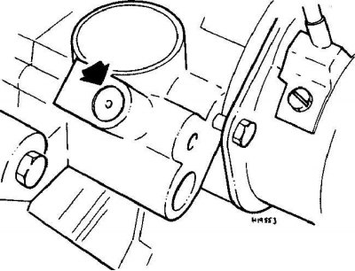
Unscrewing the inspection hole plug from the top of the STROMBERG carburetor
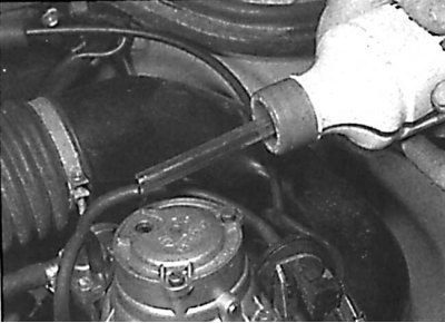
Adding oil to the piston shock absorber of the STROMBERG carburetor
1. Unscrew the inspection hole plug from the top of the carburetor (see fig. Unscrewing the inspection hole plug from the top of the STROMBERG carburetor).
2. Check that the piston damper oil level only reaches the top of the inspection hole.
3. If necessary, add oil to the lower edge of the inspection hole (see fig. Adding oil to the piston shock absorber of the STROMBERG carburetor).
4. Screw in the plug that closes the inspection hole.
Checking the idle speed and the quality of the fuel mixture
Adjustment must be made on a hot engine. In this case, all electrical consumers must be turned off and the radiator fan must not work.
Idle speed
Attention! On models with PIERBURG carburetors, the idle speed is electronically controlled and cannot be adjusted manually.
Location of STROMBERG carburetor adjusting screws
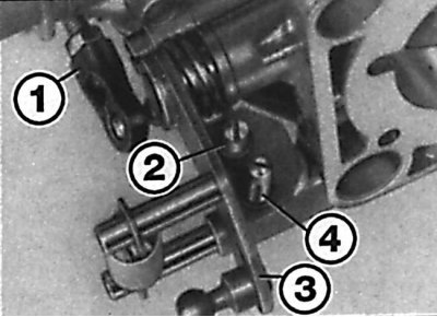
1 – connecting rod of the throttle lever; 2 - adjusting screw for adjusting fast idle speed; 3 - throttle lever; 4 – the screw of adjustment of turns of idling
1. Connect a tachometer to the engine and check the idle speed. Adjustment is made by turning the idle speed screw (see fig. Location of STROMBERG carburetor adjusting screws).
2. Increase the engine speed briefly and then re-measure the idle speed.
Checking the CO content
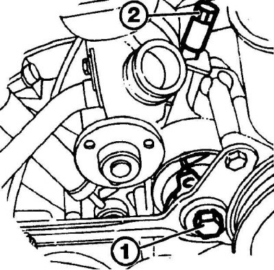
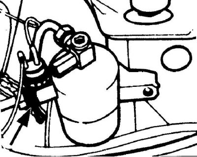
CO content adjustment
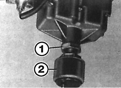
To adjust the CO content, loosen the locknut (1) and turn the fuel shut-off valve (2).
1. Insert an exhaust gas analyzer into the exhaust pipe.
2. Increase engine speed to 2,000 rpm for 15 seconds, then return engine to idle.
3. Check the CO content in the exhaust gases. To adjust, remove the plug from the fuel shut-off valve, loosen the locknut and, by rotating the fuel shut-off valve, set the required CO content (see fig. CO content adjustment).
Increased idle speed
1. Start the engine at idle speed. Check that the idle speed and CO content are correctly adjusted.
2. Manually open the throttle to run the engine at 2500 rpm. At the same time, insert a small screwdriver into the groove on the side of the throttle body, accessible after removing the plastic cover, and move the engine lever towards the engine until there is considerable resistance.
3. While fixing the engine lever with a screwdriver, release the throttle. In this case, the engine should run at high idle speed.
4. Using a tachometer, check for high idle. To adjust, turn the idle speed screw. The high idle screw is the shortest of the two screws (see fig. Location of STROMBERG carburetor adjusting screws).
5. Finally, open the throttle briefly to disengage the idle boost mechanism and allow the engine to run at normal idle.
Checking the CO content at high idle
Auxiliary Air Adjustment Screw Plug Location
1. Install an exhaust gas analyzer in the exhaust pipe.
2. Set the idle speed to high. Check the CO content in the exhaust gases. For adjustment, remove the plug from the auxiliary air set screw and, by turning the screw, set the required CO content (see fig. Auxiliary Air Adjustment Screw Plug Location).
3. Finally, briefly open the throttle to disengage the high idle mechanism and allow the engine to run at normal idle.
Models with KE-GETRONIC fuel injection system
The adjustment must be made with the engine warmed up to normal operating temperature. The adjustment must be completed before the engine temperature reaches 100°C. On later models, the idle speed is electronically controlled and adjustment is not possible without special test equipment.
When making adjustments, the air filter must be in place with the vacuum hoses and crankcase breather hose connected.
Access to idle speed screw
Access to the idle speed adjustment screw is possible through a recess on the back of the air filter housing.
Adjustment of CO content in exhaust gases
1. Install an exhaust gas analyzer in the exhaust pipe.
2. Start the engine at idle speed. On vehicles with automatic transmission, place the gear selector in the PARK position. Turn off all electrical consumers.
3. The idle speed screw is accessible through a recess on the back of the air filter housing (see fig. Access to idle speed screw).
4. Turn the adjusting screw to set the desired idle speed.
5. Turn off the engine.
6. To adjust the CO content in the exhaust gases, remove the air filter housing and, using the lever, remove the plug, then install the air filter assembly in place.
7. Start the engine and increase the engine speed to 2000 rpm for 10 seconds. Then set the idle speed.
8. Check the CO content in the exhaust gases. CO content is adjusted by turning the mixture quality adjusting screw (see fig. Adjustment of CO content in exhaust gases).
9. Finally, remove all gauges and install a new plug on the fuel mixture adjustment screw.
Checking the front suspension and steering
Front wheel hub bearing wear check
1. Raise the front of the vehicle and secure it on stands.
2. Visually inspect the ball joint dust boot and rack and pinion boot for cracks, abrasions and ageing. Any wear on these boots will result in loss of lubricant and ingress of water and dirt, resulting in rapid wear of the ball joints or steering gear.
3. Check the power steering gear hoses for chafing or aging, and pipes and hose connections for leaks. Also check for signs of a pressure leak in the protective rubber boots of the steering gear, which indicate damage to the steering seal.
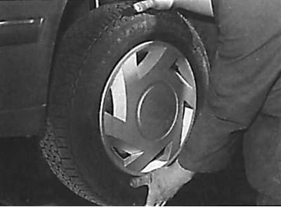
4. Raise the car with a jack, take the wheel with your hands at the 6 and 12 o'clock positions and try to shake it in a vertical plane. Very little wheel play is acceptable, but if the play is large enough, further testing is needed to establish the source. Continue pumping the wheel while the assistant applies the foot brake. If the play is eliminated or significantly reduced, it is likely that the hub bearings are damaged. If the play is still significant with the brake applied, then there is wear in the connection and suspension mount (see picture).
5. Now take the wheel to the 9 and 3 o'clock position and try to shake it in a horizontal plane. The presence of play in the horizontal plane can be caused by wear of the hub bearing or tie rod ball joints. If the outer or inner ball joint is worn, play will be evident.
6. Using a large screwdriver as a lever, check for wear in the suspension mount bushings between the suspension element and the application point. Some movement should be visible as the mount bushings are made of rubber, but excessive wear should be evident. Also check the condition of any visible parts of the rubber bushings for cracks, wear and deformation.
Shock absorber check
Check the shock absorber for any signs of fluid leaks. If a leak is found, then the shock absorber is damaged and needs to be replaced.
Attention! Shock absorbers must be changed in pairs on the same axle.
The effectiveness of the shock absorber is also tested by pressing on the corner of the body and releasing it abruptly. The body should return to its original position after it is released. If the body rises above its original position and continues to sway, it is likely that the shock absorber located on this side is out of order and must be replaced. Also check the shock absorber mount for wear.
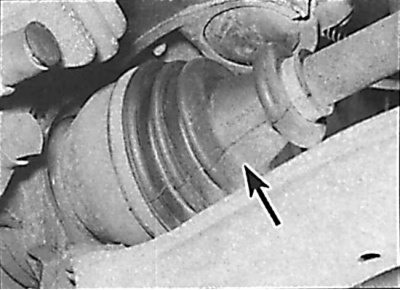
Checking the protective cover of the drive shaft
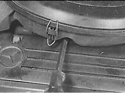
Check of a condition of a protective cover of the hinge of equal angular speeds of a driving shaft
1. Raise the rear of the car and secure it on stands.
2. While rotating the rear wheel, inspect the CV joint rubber boots, squeezing them to open the folds. Check them for cracks, which can lead to grease leakage, as well as water and dirt ingress (see picture).
3. Also check the condition of the mounting clamps, inspect the covers of the internal hinges and casings on the other side. If any damage is found, the protective cover must be replaced immediately.
4. At the same time, check the general condition of the CV joints by holding the shaft while trying to turn the wheels. Try again, holding the inner CV joint and rotating the shaft. Any noticeable play indicates wear on the pivot, wear in the shaft slots, or a loose shaft lock nut.
Checking the front brake pads
1. Apply the handbrake, raise the front of the vehicle and support it on stands. Remove the front wheels.
2. Check the thickness of the brake pads through the inspection hole in the front of the caliper.
3. If the brake pad is worn to the minimum thickness, all four brake pads must be replaced as a set.
4. Install wheels and lower vehicle.
Checking the rear brake pads
1. Raise the rear of the car and secure it on stands. Remove rear wheels.
2. Inspection of the brake pads can be done through the inspection hole at the top of the rear caliper. If the brake lining is worn to the minimum thickness, all brake pads in the set must be replaced.
3. Install wheels and lower vehicle.
Exhaust system check
1. On a cold engine, check the condition of the exhaust system along its entire length.
2. Check pipes and their connections for leaks, signs of corrosion and damage. Check that all brackets and suspension elements of the exhaust system are in good condition and evenly tensioned.
3. When moving the exhaust system of the car to the sides, check that it does not touch the car body. If not, replace the exhaust rubber mounts.
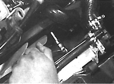
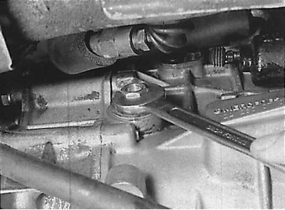
Checking the oil level in a manual transmission
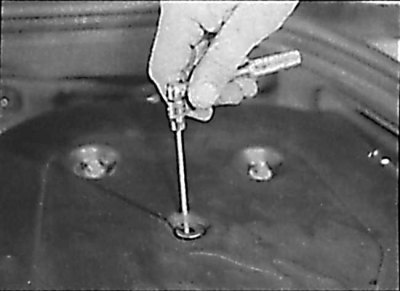
Unscrewing the oil level plug in a manual transmission
1. Install the car in a horizontal position above the inspection hole. Check the oil level no earlier than 5 minutes after stopping the engine.
2. Clean the area around the transmission oil level plug. The oil level plug is located on the front right side of the transmission. Unscrew the plug and clean it (see picture).
3. The oil level should reach the lower edge of the oil level plug hole.
4. If necessary, add oil to the gearbox through the oil level plug hole.
5. Screw in the oil level plug in the gearbox to the required torque.
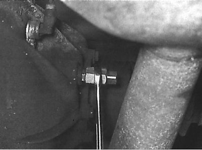
Checking the oil level in the rear final drive
Unscrewing the plug for checking the oil level in the rear final drive
1. Place the car over a viewing hole or raise it on a lift.
2. Clean the area around the oil level plug located on the left front side of the rear final drive. Unscrew the stopper (see picture).
3. The oil level should reach the lower edge of the oil level check hole.
4. If necessary, add oil to the rear final drive through the oil level plug hole.
5. Screw the oil level plug into the rear final drive and tighten to the correct torque.
6. Lower the car.