
1.8/2.0L Engines
PMS Diagram - Fuel Injection Systems (1.8/2.0 L engines)
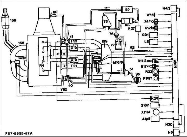
36. Thermostat (only type 124); 40. Membrane pressure regulator; 41. Membrane pressure damper (only type 124); 55. Fuel filter; 60. The system of modulating pressure of the membrane mechanism of the vacuum ignition timing regulator (only with automatic transmission); 75. Fuel tank; 77. Tank with activated carbon; 82. Pipeline under vacuum; 156. Inlet gas pipeline; 158. Catalyst; 159. Exhaust manifold; A1r5. Coolant temperature indication; B11/3. Coolant temperature sensor; B17. Intake air temperature sensor; G3/2. Oxygen sensor; K3/1. Intake manifold partial heating system (only type 124); K27. Fuel pump relay; L5. Position sensor crankshaft; M3. Fuel pump; M16/6. The executive body of the system for regulating the frequency of rotation of the engine shaft at idle N3 / 6. Engine control device (PMS); N6. Air conditioning control device; N30.ABS control device; R16/7. Equalizing plug connector; R33. CO potentiometer, only for vehicles without catalytic converter (abroad); S2/1. Ignition and starter switch; S16/1. Starter interlock switch and reversing light switch; T1/1. Ignition coil 1 for cylinders 1 and 4; T1/2. Ignition coil 2 for cylinders 2 and 3; W14. Mass point on ABS hydraulic unit holder; X4/10. Connecting block; X11/14. Central plug for connecting the diagnostic stand; X12/3. Terminal 30/15 of connecting block without fuse; Y62. Valve injectors
Attention! Instead of a thermostat (36) and regeneration valve (51), engine type 202 (C-class) equipped with a changeover valve which is directly controlled by the PMS controller.
Fuel from the fuel tank is drawn by the electric fuel pump and delivered to the valve injectors through the fuel filter and distribution line. The pressure regulator on the distribution pipe maintains a constant pressure in the fuel system depending on the vacuum in the intake pipe. Valve injectors are controlled by electrical systems and fuel is injected intermittently, jogging into the intake pipe ahead of the intake valves. In this case, the valve injectors are controlled semi-sequentially, i.e. for each revolution of the crankshaft, it simultaneously injects two valve injectors alternately, respectively. In the event of malfunctions in the ignition system, the corresponding group is switched off to protect the catalyst.
Air is sucked in by the engine through the air filter and the inlet gas line. The vacuum in the inlet gas line is registered by a sensitive element and serves as a criterion for the quantity of the injected quantity. Since the vacuum depends on the position of the throttle valve (accelerator pedal position), the amount of air taken in is a measure of the actual engine load. Therefore, this control system is called R-control, where "R" is the physical quantity of pressure.
The control system regulates the injection time and thus the amount of injected fuel in accordance with the vacuum and the given engine speed. With a relatively long opening of the valve injector, more fuel is injected. An additional sensor and actuators also take care of the measured fuel quantities in extreme driving situations.
The fuel injection system controller regulates the idle speed of the engine with the help of its adjuster, which regulates the amount of air in idle speed around the throttle valve. This achieves a constant engine speed at idle, regardless of whether direct additional consumers such as power steering or an air conditioning compressor are connected.
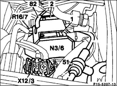
1. Multi-pin plug (side of the car); 2. Multi-pin plug (on the engine side); 83. The pipeline to the inlet gas pipeline, which is under vacuum; R16/7. Equalizing plug for fuel matching; X12/3. Terminal 15 of connection block without fuse
Engine control device (N3/6) located in the engine compartment on the left side.
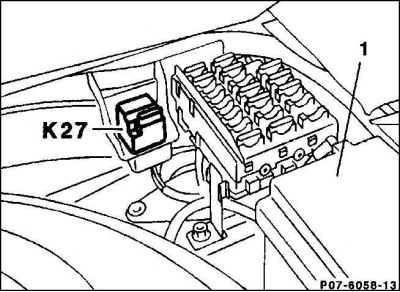
Fuel pump relay (27) supplies electricity to the fuel pump. The safety circuit interrupts the current supply as soon as there are no more speed pulses, for example if the motor has been stopped. The relay is located in the trunk on the right side; 1 - battery.
Oxygen sensor (Lambda probe) measures the oxygen content in the exhaust gas stream and sends the corresponding voltage signals to the control unit. The control device then regulates the injection quantity of fuel in such a way that the exhaust gases are optimally afterburned on the catalytic converter.
The intake air temperature sensor measures its temperature, the second temperature sensor on the body of the coolant supply regulator changes the temperature of the latter.
The solenoid valve for venting the fuel tank is controlled depending on the engine operating mode. The released fuel vapors are captured by an activated carbon filter and fed through the valve for combustion. Therefore, thanks to the filter filled with activated carbon, fuel vapors are mostly economically used and do not enter the atmosphere.
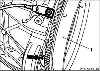
flywheel (1) and inductive sensors are installed on the intake camshaft drive gear (L5). They transmit information about the actual engine speed and crankshaft position to the fuel injection system control unit.
The ignition system no longer has any moving parts and is therefore not subject to wear down to the spark plugs. If you turn off in the engine compartment (pull off) equalizing plug connector, it is possible to refuel with lower quality fuel. If you refill with gasoline for vehicles with high performance engines (octane number 96–98, not less than 95 ROZ), reattach the equalization plug.