



Sequence of works


1. Raise and secure the vehicle.
2. Remove the lower engine guard.
3. To avoid disturbing the balance of the cardan shaft during reassembly, mark its position in the following places:
- position of the propeller shaft flange (fig. 6.16, arrows) relative to differential;
- the position of the cardan shaft, damper and disc joint relative to the gearbox and each other.
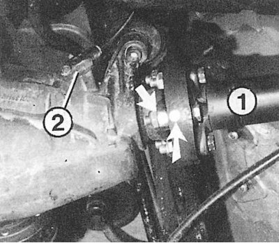
Fig. 6.16. Marking locations of the rear propeller shaft (arrows): 1 – rear propeller shaft; 2 – differential speed sensor
4. Remove the rear section of the exhaust system.
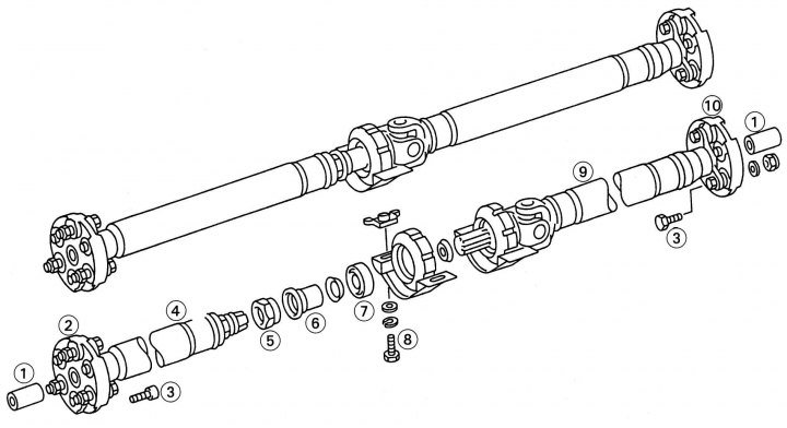
Fig. 6.15. Cardan transmission parts: 1 – centering sleeve; 2, 10 – elastic coupling; 3 – bolt, 45 Nm; 4 – front shaft; 5 – locking nut; 6 – rubber cuff; 7 – bearing; 8 – bolt, 25 Nm; 9 – rear shaft
5. Loosen bolt 8 (see fig. 6.15) fastening of the support bearing 7, having previously marked the position.
6. Unscrew the mounting bracket from the tunnel.
7. Remove the protection over the exhaust system.
8. Loosen the locking nut SW 41/42 on the sliding part (front and back) cardan shaft.
9. Unscrew the cardan shaft from the gearbox flange so that the disc joint remains on the shaft (bolt head SW 15, nut SW 17).
10. Loosen the driveshaft fastening to the differential flange (three bolts SW 15, nuts SW 17) so that the CV joint remains on the shaft.
11. If the shaft sticks to the differential flange, free it with gentle blows.
12. Slightly push the driveshaft parts together and remove it from the flanges.
13. Leave the back of the shaft hanging down.
14. Unscrew the bolts 8 securing the support bearing.
15. Remove the propeller shaft from the center tunnel in the underbody of the vehicle.
16. Press centering bushings 1 from couplings 2 and 10.
17. When reinstalling, fill the bushing cavities with universal grease.
18. When reinstalling, first fit the front shaft onto the gearbox flange, observing the markings. Use new nuts to secure.
19. Install the support bearing without tightening it completely.
20. Following the markings, screw on the rear shaft. Use new self-locking nuts, tighten them to a torque of 45 N·m.
21. Tighten the front shaft to flange mounting bolts to 25 Nm.
22. Tighten the support bearing mounting bolts to a torque of 25 N·m. The rear wheels of the vehicle must be on the ground. If the rear axle is unloaded, tighten the fastening only if the corresponding marks have been previously applied.
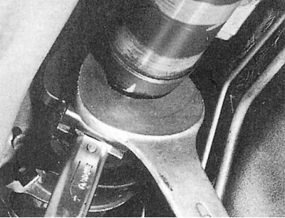
Fig. 6.17. Tightening the locking nut with a SW 41 open-end wrench. Observe a tightening torque of 30–40 Nm, otherwise the propeller shaft will hum
23. Tighten the locking nut SW 41/42 to a torque of 30–40 Nm (Fig. 6.17).
Noises in the driveshaft
Vibrations and humming indicate an imbalance in the driveshaft, and the absence of balancing plates on the shaft allows us to conclude that the balance is disturbed. Both parts of the shaft are carefully balanced relative to each other. Disassembling the driveshaft without initially marking the original position disturbs the balance.
The imbalance of the running gear is also possible due to breakage or rupture of elastic disk joints (CV joints). Loose fixation of the centering bushings indicates wear of the joints. Also unacceptable is the expansion from wear of the fastening holes in the flanges of the gearbox and reducer.
Whistling sounds may be the result of a worn or failed support bearing.
Squeaking and grinding noises are usually the result of too much play in the connection between the two parts of the driveshaft, or the centering bushings do not have enough lubrication.