
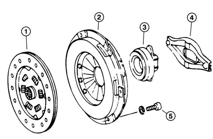
Pic. 6.1. Clutch components and parts: 1 - driven disk; 2 - pressure plate; 3 - clutch release bearing; 4 - clutch release lever; 5 – a bolt of fastening of a casing of coupling with a pressure disk
Brake fluid is used to actuate the clutch. It is in the same reservoir as the brake fluid. The tank is divided into two chambers: one for the brake system, the other for the hydraulic clutch. These systems work separately so that a leak in the hydraulic clutch does not affect the braking system.
The most important components and parts of the clutch
engine flywheel. Rigidly connected to the crankshaft. All engines have a so-called dual mass flywheel.
Slave disk 1 (pic. 6.1). It is put on the input shaft of the gearbox. Friction linings are riveted to the clutch disc on both sides.
Clutch cover with pressure plate. Inside the clutch housing is a pressure plate, which, by means of a diaphragm spring, presses the clutch plate against the flywheel. The clutch cover with the clutch pressure plate is rigidly bolted to the flywheel.
Clutch Release Bearing. When you press the clutch pedal, the hydraulic actuator presses the clutch release bearing against the petals of the diaphragm spring. Due to this, the clutch disc can rotate freely on the gearbox input shaft, and the transmission of torque from the engine to the gearbox is interrupted.
Clutch Master Cylinder. It is located next to the axle of the clutch pedal, connected to the pedal by a push rod. When you press the clutch pedal, the rod pushes the piston connected to it into the master cylinder. Pressure is created inside the cylinder, which is transmitted through a hose attached to the cylinder to the clutch slave cylinder and moves the piston located in the slave cylinder.
Working cylinder. Mounted horizontally on the side of a manual gearbox and transmits power when the clutch pedal is depressed. The rod of the working cylinder extends and presses the release lever, which drives the clutch release bearing.