



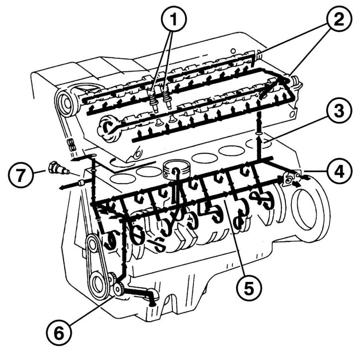
Fig. 4.31. Lubrication system: 1 – hydraulic tappets, 2 – oil channels for supplying oil to the valve mechanism, 3 – main oil channel from the engine block to the cylinder head, 4 – oil filter flange, 5 – channel to the oil filter, 6 – oil pump, 7 – oil regulator of the control chain tensioner
The engine lubrication system (Fig. 4.31) is designed for:
1. Lubrication of engine units and assemblies. Creation of an oil film between moving surfaces ensures minimal wear of surfaces (pistons and cylinders, main bearings, valve drive and other components).
2. Elimination of gaps between the piston, piston rings and working surfaces of the cylinder.
3. Cooling of parts such as pistons, crankshaft bearings.
The oil pump supplies oil under pressure to the appropriate channels, from where it enters the oil filter for cleaning. When the filter is clogged, the drain valve starts working, which opens the auxiliary circulation channel at a certain pressure. Uncleaned oil causes rapid wear of the bearings.
From the filter, the lubricant flows through holes in the cylinder block to the bearings of the crankshaft, connecting rod, auxiliary shaft and valve mechanism in the cylinder head.
The cylinder walls and piston pins are lubricated with oil that enters through the connecting rods. Separate oil nozzles serve to cool the pistons.