



Contents: Interior lighting ↡ Sun visors ↡ Cosmetic mirror ↡ Glove box ↡ Drawer on the middle console ↡ Drawers under the armrest ↡ Models with automated heating system ↡ Changing the angle of the armrest ↡ Drink holder ↡ Ashtrays ↡ Cigarette lighter ↡ Telematics services "Mercedes-Benz"…↡ Telephone - general information ↡ Phone shutdown delay time ↡ Radiotelephone in the armrest ↡ Radiotelephone on the dashboard ↡ Safety net for luggage in the front…↡ Roof rack ↡ Folding the rear bench seat ↡ Download rules ↡ Cargo securing device ↡ Removal and installation the rear…↡ Plug-in towing hitch ↡ Key No ↡ Removal the plug ↡ Removal the plug socket ↡ Installing a ball head ↡ There is a risk of accident! ↡ Removal the ball head ↡ Storing the ball head ↡ Care instructions ↡ Trailers with 7-pin plug ↡ Power supply from the network ↡
Interior lighting
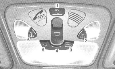
1 - Ceiling lights in the rear of the cabin.
Turning the rear lights on and off: Press the button.
2 - Front right reading light.
Turn the reading light on and off: press the button.
The right reading light is turned on or off.
3 - Turn on the automatic function: Press the key switch.
The lights remain off even if the vehicle is unlocked, a door is opened or the key is removed from the ignition switch.
4 - Turning on the automatic function: Move the key switch to the middle position.
If the key is removed from the ignition switch in the dark, the lights turn on and then turn off after a time delay.
The lamps are switched off if one door is opened in the dark. When one of the front doors is opened, the lamp in the front part of the cabin is switched on; when one of the rear doors is opened, the lamps in the rear part are switched on.
When the doors are closed, the lamps turn off after a time delay.
If the car is unlocked in the dark, the lights turn on and then turn off after a time delay.
5 - Manually turning on the front ceiling light: Press the key switch. As long as the key switch is pressed, the front ceiling light remains on.
To turn off the front ceiling light: Move the key switch to position 3.
Note: The delay time after which the lamps should turn off after the key is removed from the ignition switch can be set in the "LIGHTING" menu of the "Custom Installation" system, in the installation menu "INT. ILLUMINATION DELAYED SWITCH-OFF" (TIME DELAYED INTERIOR LIGHT TURN-OFF) (Chapter Multifunctional steering wheel, universal display).
With one door open and the key in position 0 or removed, the lights turn off approximately 5 minutes after all the vehicle's electronic equipment has returned to its original state.
6 - Front left reading light: Press the button.
The left reading light is switched on or off.
Sun visors
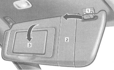
To protect against glare from the front: Fold down the sun visors.
To prevent glare from the side window: Remove the sun visor from the holder (1) on the inside and move it to the side.
Note: The press pocket (2) is used, for example, to store cards.
Cosmetic mirror
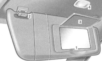
1 - Illuminated vanity mirror in sun visor.
Opening: The sun visor must be locked in the holder (2). Fold the cover (3) upwards. The lighting (4) switches on.
Closing: Lower the lid down.
Glove box
The glove box can be unlocked and locked with the emergency key.
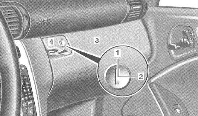
1 - Unlocking
2 - Locking
3 - Glove box
4 - Handle
Opening: Pull the handle (4) and open the glove compartment lid.
Note: There is a compartment for glasses in the glove compartment lid.
Radio/COMAND system with CD changer: The CD changer is located in the glove compartment.
Drawer on the middle console
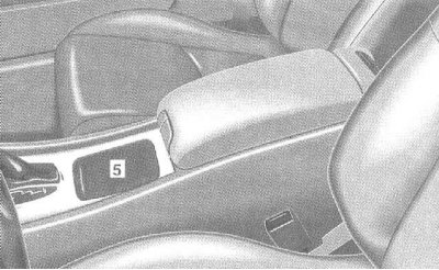
5 - Box on the middle console
Opening: Slide the lid back.
Closing: Slide the lid forward.
Note: The storage compartment in front of the console armrest contains a cigarette lighter, coin compartment and cup holder.
Article borrowed from the web portal MercedesMan.ru
Drawers under the armrest
Models with automatic air conditioning or automatic air conditioning with comfort control
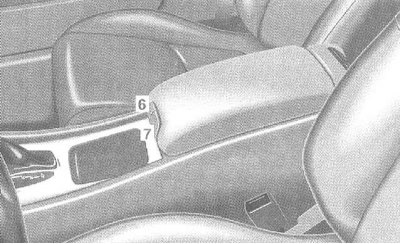
6 - Box in the armrest (for phone)
7 - Drawer under the armrest
Opening: Pull the button (6) to lift the armrest.
Closing: lower the armrest down and lock it.
Note: The compartment lid contains a compartment for storing plastic cards.
Models with automated heating system
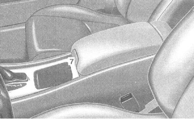
7 - Drawer under the armrest
Opening: Pull the button (7) to lift the armrest.
Closing: lower the armrest down and lock it.
Note for models with automatic air conditioning:
The box can be air-conditioned (Section Automatic heater and air conditioner. Ventilation. Independent heater).
The temperature in the box can increase significantly due to the limited space. Therefore, when transporting heat-sensitive cargo, it is necessary to close the ventilation deflector of the switched-on heating.
Models with automatic air conditioning:
Do not cover the ventilation deflector in the glove compartment with objects.
Changing the angle of the armrest
(models with automatic air conditioning or automatic air conditioning with comfort control)
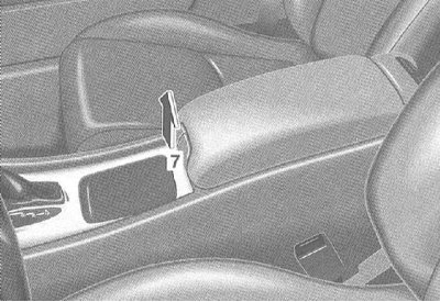
Raise the armrest to the required position without pressing the button (7). To lower it, pull the button (7).
Drink holder
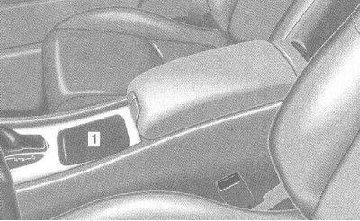
1 Drink holder in the storage compartment on the center console
Opening: Slide the lid back.
Closing: Slide the lid forward.
Ashtrays
Middle console
Opening: Press lightly on the bottom edge of the lid, the ashtray opens.
Removal the insert
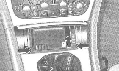
Models with manual transmission: Shift the gearshift lever to 2nd gear.
Automatic transmission models: Shift to D.
Push the ashtray forward (1) until it releases from the locking position. Remove the insert.
Installing the insert
Press the insert until it locks into place.
Rear of the cabin
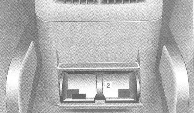
Opening
Grasp the top of the lid and pull it out - the ashtray opens.
Removal the insert
Press the retaining pad (2) down and remove the insert.
Installing the insert
Install the insert and close it tightly.
Cigarette lighter
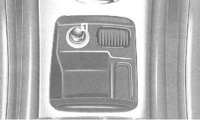
1 Cigarette lighter on the center console
The cigarette lighter in the center console is located in the storage compartment in the center console.
Note: The ashtray is located in front of the AT selector lever/gear shift gate.
Turn the key in the ignition switch to position 1 or 2.
Press the cigarette lighter in: it will pop out automatically as soon as the coil is heated.
The cigarette lighter socket can be used to connect special accessories.
Telematics services "Mercedes-Benz" (teleAid, DynAPS, FCD systems)
With a dynamic target tracking system (dynASP system) and the FCD vehicle floating data system (Floating Car Data):
If you are registered as a user of telematics services "Mercedes-Benz", the central control room of these transport and technical services regularly and automatically transmits free short messages (SMS) through your radio network.
In the case of using PrePaid cards with advance payment (for using mobile phones without concluding a corresponding contract with the provider) such services for the transmission of the above-mentioned short messages (SMS) are subject to payment by deduction from the amount on your card.
Telephone - general information
The use of radio telephones in the vehicle is permitted only if they are connected to a separate external antenna.
Phone shutdown delay time
If the key is removed from the ignition switch, the phone remains on for about 10 minutes (delay time).
If you use the phone during this time, the phone switches off approximately 10 minutes after the end of the call.
Changing the phone's turn-off delay time:
By means of an additional entry in the phone book, the delay time of the telephone switch-off can be changed in the range between one and sixty minutes. (Entering an entry in the phone book - separate "Telephone Operating Guide").
When the indication appears "NACHLAUFZEIT" (DELAY TIME) and enter the number (minutes) between "1" and "60". If you did not enter the number or entered the wrong number, then the delay time is still approximately 10 minutes.
Radiotelephone in the armrest
Installing the phone
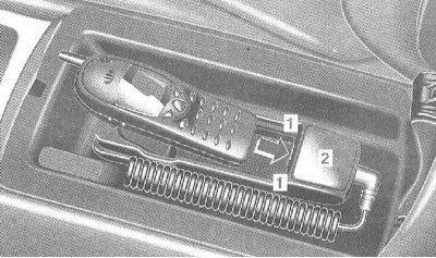
Open the phone compartment in the armrest.
Insert the lower part of the phone into the protrusions (1) of the receiving socket (2).
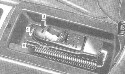
At the front, press the phone down (3). The flap (4) automatically locks, moving to the right.
Only in this position is the telephone connected to the speakerphone.
(Using the phone via the multifunction steering wheel - see Section Multifunctional steering wheel, universal display).
If the battery is not fully charged, the charging process starts as soon as the key is inserted into the ignition switch.
Note: The receiving socket (2) is suitable for the following phones: NOKIA 5110, NOKIA 5130, NOKIA 6110, NOKIA 6130, NOKIA 6150.
Using the phone via the mobile radiotelephone control panel
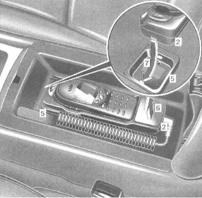
Removing the phone together with the holder: Pull the receiving socket (2) with the phone upwards (6) from the holder lock (5).
Installing the phone together with the holder: Insert the receiving socket (2) with the phone (7) into the holder lock (5) and press down until you hear a distinctive click.
Using the phone
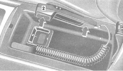
The receiving jack (2) has the function of a telephone handset (arrows) for making telephone conversations.
(Using the phone - separate "Phone Operating Guide").
Note: The telephone handset function is disabled as long as the telephone is inserted into the receiver jack (2).
Telephone conversations are only possible through the telephone handset (arrows).
Taking out the phone
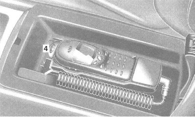
Move the flap (4) to the left until it locks. Pull the phone forward.
Radiotelephone on the dashboard
Installing the phone
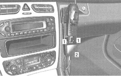
Insert the lower part of the phone into the protrusions (1) of the receiving socket (2).
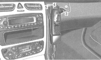
At the top, press the phone forward (3). The shutter (4) automatically locks, moving to the right.
Only in this position is the telephone connected to the speakerphone.
If the battery is not fully charged, the charging process starts as soon as the key is inserted into the ignition switch.
Note: The receiving socket (2) is suitable for the following phones: NOKIA 5110, NOKIA 5130, NOKIA 6110, NOKIA 6130, NOKIA 6150.
Using the phone via the mobile radiotelephone control panel
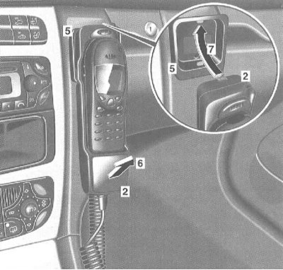
Removing the telephone together with the receiving socket: Pull the receiving socket (2) with the telephone back (6) from the holder lock (5).
Installing the telephone together with the holder: Insert the receiving socket (2) with the telephone (7) into the holder lock (5) and press forward until it clicks into place.
Using the phone:
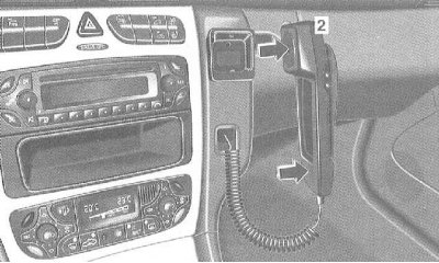
The receiving socket (2) has a full telephone handset function (arrows).
The telephone handset is switched off as long as it is inserted into the jack (2).
Taking out the phone
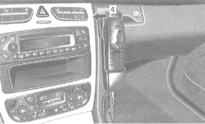
Move the shutter (4) until it locks. Remove the phone upwards.
Safety net for luggage in the front passenger footwell
The luggage safety net is intended for the transportation of light loads only.
Heavy, fragile and sharp-edged items must not be transported in the luggage safety net.
The luggage safety net cannot protect the cargo in the event of an accident.
Roof rack
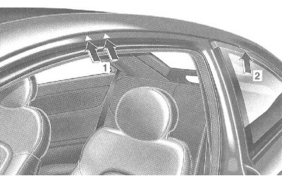
At the front, secure the luggage rack only to the roof rails between the markings (1), and at the rear, only to the groove (2) of the rubber strip.
Folding the rear bench seat
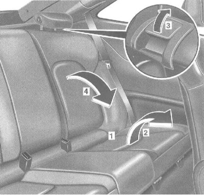
Flipping back
Slide the head restraints in and fold them back (Section Seats).
Pull the release handle (1), fold the seat cushion (2) forward.
Pull the lever (3) and release the seat back.
Fold the seat back down (4).
Setting the backrest to a sitting position
Fold the seat back until it locks into place.
Fold the seat cushion back.
If necessary, fold the headrest up and install it.
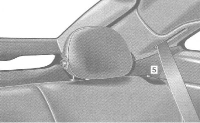
When the rear seat back is not locked, the locking indicator (5) is visible in the release levers.
Download rules
The dynamic properties of a loaded vehicle depend on the distribution of the load.
Therefore, load the vehicle in accordance with the drawing.
The total weight of the transported cargo, including passengers, must not exceed the full standard weight and the permissible load on the bridge.
Place heavy loads in the lower front part of the trunk.
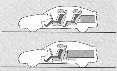
Move the load towards the back of the rear seats or towards the forward-folded seat cushion.
Cargo of any kind must be secured with fastening means that have sufficient resistance to tearing and abrasion.
Protect sharp edges with soft material.
Fastening means can be purchased at any service station "Mercedes-Benz".
Cargo securing device
The trunk has eyelets for fastening.
Secure your luggage using the eyelets.
Do not use elastic bands or nets to secure cargo, as they are only intended to prevent lighter loads from moving.
Fasteners must not be passed over sharp edges or corners.
Protect sharp edges with soft material.
Removal and installation the rear shelf
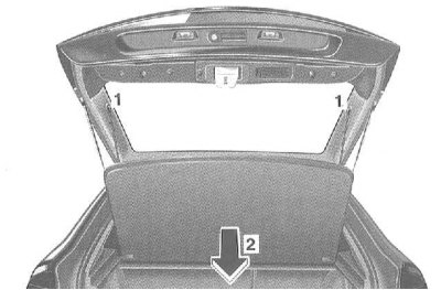
Removal
Unhook the fastening straps (1).
Pull the rear shelf back (2).
Installation
Hang the rear shelf onto the mounting element.
Attach the mounting straps to the trunk door.
Plug-in towing hitch
(Towing a trailer - see Section Vehicle control and auxiliary systems).
(Mounting dimensions and loads are given in "Specifications").
Note: To purchase a spare key, you will need the key number.
Key No
A spare key can be purchased at a service station "Mercedes-Benz".
Removal the plug
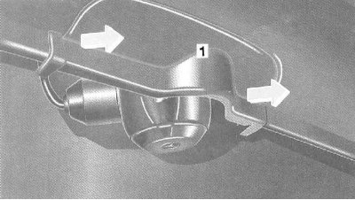
Remove the plug (1) on the bumper from below and take it out.
Removal the plug socket
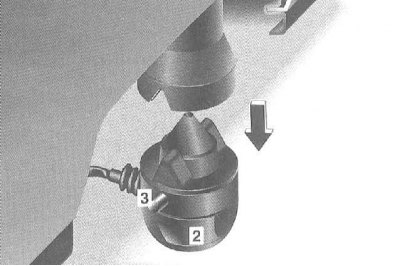
Press the release button (3) and pull the plug (2) downwards out of the ball head mounting socket.
The ball head is located in the spare wheel in an additional compartment under the boot floor.
Installing a ball head
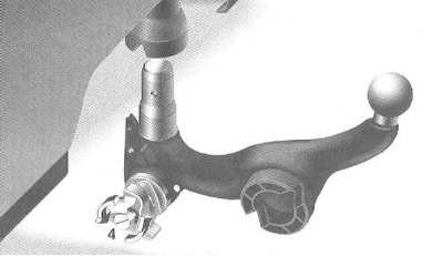
Insert the key (4) into the ball head lock and turn it counterclockwise.
Pull the handle away from the ball head and rotate it clockwise until it locks in place. The white dot on the ball head aligns with the red area on the handle.
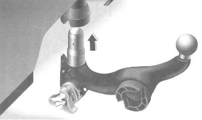
Insert the ball head vertically into the ball head socket until it locks automatically. The handle automatically rotates so that the green area (5) on the handle matches the white marking on the ball head.
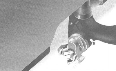
Turn the key in the lock in the direction of the arrow (lock).
Remove the key and replace the protective cap.
There is a risk of accident!
When driving with a trailer, the ball head must be locked and the key removed. Only in this case is the ball head protected from disengaging while driving.
If the ball head cannot be locked and the key cannot be removed, remove and clean the ball head. If the ball head cannot be mounted (locked) even after cleaning, contact one of the service stations "Mercedes-Benz" to check the towing hitch as a whole.
In this case, the towing hitch cannot be used to tow a trailer, as reliable operation is not ensured.
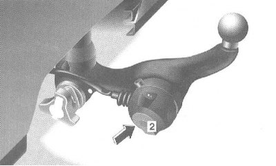
Fix the socket (2) into the mounting socket on the ball head.
Note: When not using the towing hitch, it is recommended to remove the ball head.
Removal the ball head
Press the release button (3) on the socket (2) and remove the socket from the ball head.
Remove the protective cap and unlock the handle with the key (4).
While holding the ball head, pull the handle up and rotate clockwise until it reaches the red zone and locks into place.
Remove the ball head downwards.
Insert the plug socket (2) into the ball head mounting socket and press until it locks into place.
Place the plug (1) on top and secure it by pressing from below.
Note: Make sure the plug socket (2) is securely seated.
Storing the ball head
Place the ball head with the key inserted into it into the slot in the spare wheel.
Care instructions
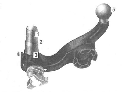
If dirty, the ball head and the ball head mounting socket should be cleaned to ensure easy installation and removal at all times.
Note: Do not clean the ball head with a high pressure car wash or use solvents.
After cleaning, apply a thin layer of oil or grease to the following areas:
- 1 fixing balls,
- 2 guide pins,
- 3 guide surfaces,
- 4 release lever,
- 5 ball head, as well as to the ball head bracket on the vehicle.
Lubricate the lock with acid- and resin-free oil.
Trailers with 7-pin plug
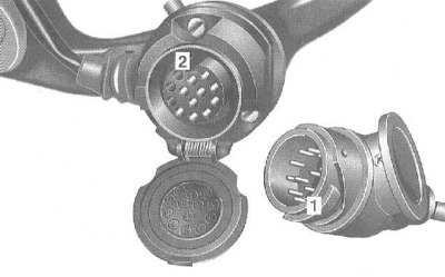
A plug connection between a vehicle with a 13-pin socket and a trailer with a 7-pin plug can be achieved using an adapter cable.
The adapter cable can be purchased at any service station "Mercedes-Benz".
- 1 Performance
- 2 Groove
Installation
Lift the cover. Insert the plug with the protrusion into the groove and turn it to the right until it stops. Let the cover lock.
Secure the adapter cable loosely to the trailer using cable tie-down straps.
Power supply from the network
Your vehicle has the ability to connect to the vehicle's power supply. If the trailer requires power from the vehicle's power supply, the appropriate fuse must be installed (Chapter On-board electrical equipment).