



Contents: Main fuse box ↡ Main fuse box ↡ Fuse box F34 ↡ Fuse box F35 ↡ Driver's seat fuse box ↡ Fuse box F7 ↡
Main fuse box
Attention: fuses can only be replaced after the cause of their blown condition has been eliminated.
The main fuse box is located in the engine compartment on the right.
To open the cover, bend the latches in the directions indicated by the arrows.
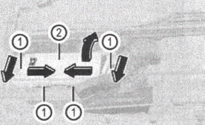
Figure 93
1. Tongue
2. Lid
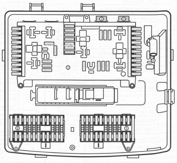
Figure 94
1. Main fuse box
2. Fuse socket F4
3. Fuse socket F5
4. Main fuse F1
5. Fuse box F34
6. Fuse box F35
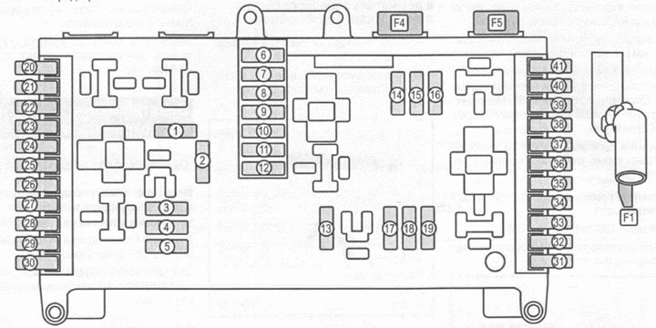
Figure 95
Main fuse box
Main fuse box
| Number | Consumer | Denomination |
| 1 | Front windshield wiper | 30 A |
| 2 | Sound signal | 15A |
| 3 | Brake light switch | 5A |
| 4 | Heater | 7.5 A |
| 5 | Diagnostic block | |
| 6 | Automotive components | 5A |
| 7 | Rear wiper | 30 A |
| 8 | Chain. 87 (1) | 10A |
| 9 | Chain. 87 (2) | 15A |
| 10 | Chain. 87(3) | 16 A |
| 11 | Chain 30 Z electric motor | 7.5 A |
| 12 | Rear window heating | 30 A |
| 13 | Ignition switch and anti-theft system | 7.5 A |
| 14 | Brake system | 7.5 A |
| 15 | Headlight beam angle adjuster | 5A |
| 16 | Starter | 25 A |
| 17 | Fuel pump | 15A |
| 18 | Cigarette lighter | 15A |
| 19 | Radio | 5A |
| 20 | Ignition system (gasoline engine car) | 15A |
| 21 | Power supply for automatic transmission control system | 7.5 A |
| 22 | Tachograph | 7.5 A |
| 23 | Airbag control unit | 10A |
| 24 | Not used | |
| 25 | Trailer control unit | 5A |
| 26 | Isolation relay | 5A |
| 27 | Chain. 15 | 5A |
| 28 | Drive control device | 10A |
| 29 | Not used | |
| 30 | Not used | |
| 31 | EDW System Sound Signal | 10A |
| 32 | Mobile Phone VICS Connection | 5A |
| 33 | Airbag, AKSE system | 10A |
| 34 | Chain. 15 | 5A |
| 35 | Sliding roof control and drive unit | 7.5 A |
| 36 | Electrically adjustable seat positions | 10 A |
| 37 | Passenger mirror illumination | 7.5 A |
| 38 | Interior of the body behind the front seats | 7.5 A |
| 39 | Not used | |
| 40 | CDI system control unit | 10A |
| 41 | CDI system control unit | 10A |
| F1 | Circuit 30 on-board network, generator | 150A |
| F4 | Air conditioner fan | 60 A |
| F5 | Secondary fan | 40 A |
[Full article available on the resource: www.mercedesman.ru]
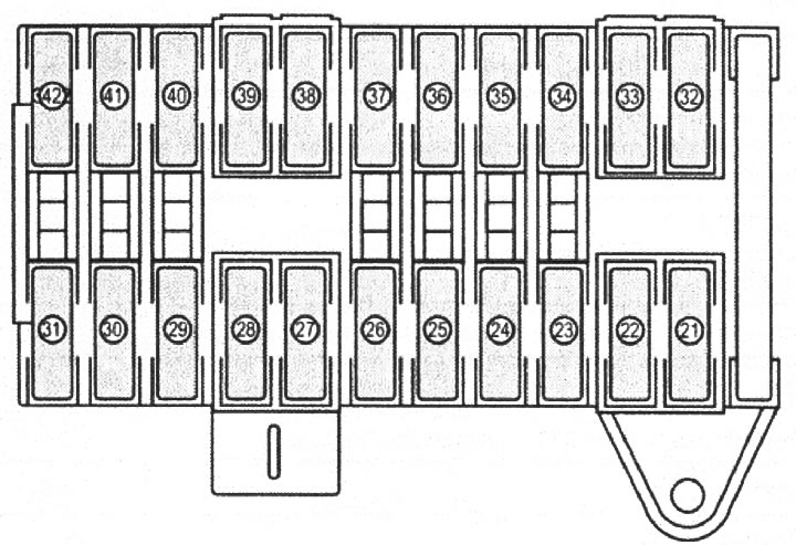
Figure 96
Fuse box F34
| Number | Consumer | Denomination |
| 21 | Central light switch and overhead control panel | 5A |
| 22 | Rear seat consumers | 7.5A |
| 23 | Lighting plafond | 10 A |
| 24 | Sliding roof (hatch) drive | 7.5A/25A |
| 25 | Panoramic sliding roof drive | 25 A |
| 26 | Radio | 5A |
| 27 | Air Conditioning, Rear Consumers | 7.5 A |
| 28 | Rear seat consumers | 15A |
| 29 | Mobile phone/UNGUATRONIC system | 7.5 A |
| 30 | Heated seats | 30 A |
| 31 | Tachograph | 5A |
| 32 | Not used | |
| 33 | Diagnostic block | 10 A |
| 34 | Not used | |
| 35 | Tempmatik/air conditioning system | 5A |
| 36 | Headlight washer | 30 A |
| 37 | EDW Sound Signal | 10 A |
| 38 | Locking steering columns | 20 A |
| 39 | Fan | 40 A |
| 40 | ABS control unit | 25 A |
| 41 | ABS control unit | 40 A |
| 42 | Radio/COMAND system | 15A |
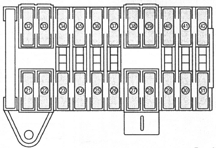
Figure 97
Fuse box F35
| 21 | 12V power supply for consumers of the left middle pillar of the passenger compartment | 15A |
| 22 | 12V power supply for consumers of the left middle pillar of the passenger compartment | 15 A |
| 23 | Trailer electrical connector | 30 A |
| 24 | Sight identification device | 25 A |
| 25 | Adjusting the driver's seat position | 30 A |
| 26 | Adjusting the passenger seat position | 30 A |
| 27 | Electric drive of the left sliding door | 30 A |
| 28 | Electric drive of the right sliding door | 30 A |
| 29 | Fan | 30 A |
| 30 | Air suspension power supply | 40 A |
| 31 | PARKTRONIC system | 10A |
| 32 | Tire pressure monitoring system | 5A |
| 33 | Not used | |
| 34 | Mobile Phone/VICS+ TV Amplifier | 5A |
| 35 | Parking heater control unit | 20 A |
| 36 | Not used | |
| 37 | Air conditioner | 5A |
| 38 | Not used | |
| 39 | Not used | |
| 40 | 12V power socket | 15A |
| 41 | Control unit for additional direction indicators on the roof | 10A |
Driver's seat fuse box
To open the cover of the compartment under the driver's vision, turn the lock (1).
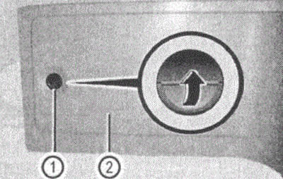
Figure 98
1. Rotary lock
2. Lid
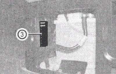
Figure 99
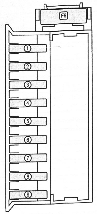
Figure 100
Fuse box F7
| Number | Consumer | Denomination |
| 1 | Control panel on the left door | 25 A |
| 2 | Control panel on the right door | 25A |
| 3 | PSM control unit | 25 A |
| 4 | PSM control unit | 25 A |
| 5 | 12V power outlet in passenger seat compartment | 15 A |
| 6 | Not used | |
| 7 | Parking heater timer and illumination | 7.5 A |
| 8 | Parking heater | 25 A |
| 9 | Parking heater | 25 A |
| F6 | SAM-SRB | 80 A |