



Removal
1. Disconnect the negative cable from the battery.
2. Remove the air intake pipe.
3. Disconnect the M33.1 connector by removing the clamp (arrow) (see figure 2.125).
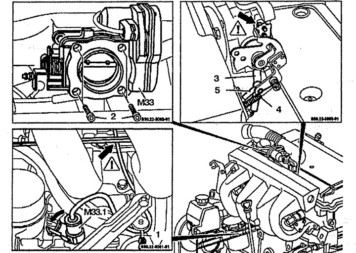
Figure 2.125. Idle drive:
1. Fixator,
2. Bolt,
3. Vacuum tube,
4. Return spring,
5. Connecting rod,
MZZ. Idle speed control valve,
M33.1. Connector.
4. Disconnect the retainer 1.
5. Lift the wires up.
6. Disconnect vacuum tube 3 and secure it above connecting lever 5.
7. Disconnect the return spring 4.
8. Disconnect connecting rod 5 from the idle speed control MZZ. The contact switch must be in the "ON" position (arrow).
9. Remove the idle speed control valve MZZ.
Installation
10. Installation is carried out in the reverse order of removal. Make adjustments.
Adjustment
11. Adjust the runout of cable 4 between spring 1 and guide 2 on lever 7 by turning nut 3 (see figure 2.126). The gap between the spring and the guide should be 0.5-1.0 mm.
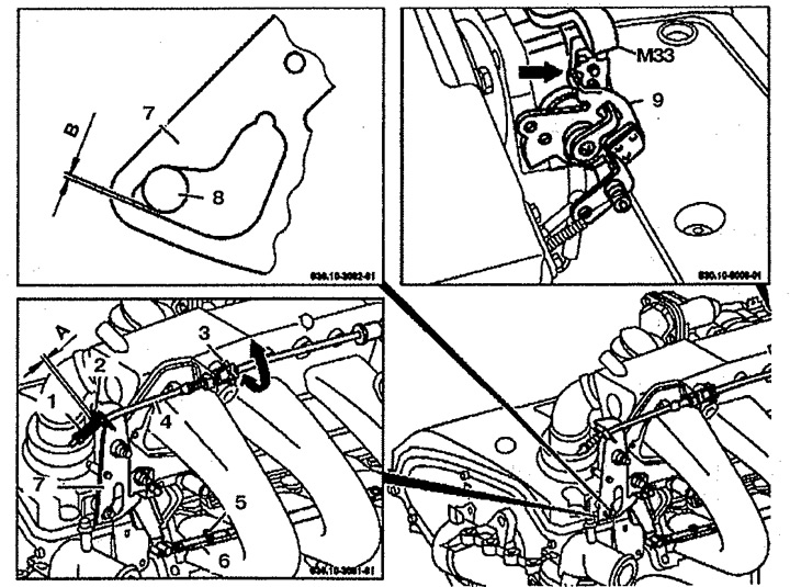
Figure 2.126. Adjusting the idle drive:
1. Spring,
2. Guide,
3. Adjusting bolt,
4. Cable,
5. Clamp bolt,
6. Connecting rod,
7. Lever,
8. Roller,
9. Support lever.
Idle speed drive,
"A". Gap in the drive cable,
"B". The gap between the roller and the lever.
12. Loosen bolt 5 of the connecting rod clamp 6.
13. Rotate lever 9 on the M33 drive until it stops.
14. Rotate lever 7 counterclockwise until roller 8 reaches the stop at the end of the lever without any gap. The gap between the lever and the roller should be no more than 0.5 mm.
15. Tighten bolt 5 of the connecting rod clamp 6.
16. Check the clearance in the idle speed drive cable 4 between spring 1 and guide 2 on lever 7 and, if necessary, adjust again.