
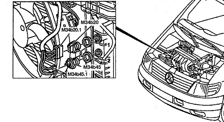
Pic. 2.111. The location of the components of the engine management system on the body:
A13. The engine control unit,
A13.1. Connector 1 control unit (label "F"),
A13.2. Connector 2 control unit (label "M"),
A13.3. crankshaft position sensor connector,
K39. fuel pump relay,
R11. Diagnostic connector (38 finger),
R27. Control unit resistor.
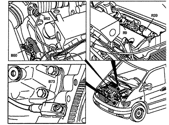
Pic. 2.112. The location of the components of the engine management system on the engine:
B60. coolant temperature sensor,
B63. Inlet air temperature sensor,
B73. crankshaft position sensor,
R9. Ignition coil 1 (2 and 3 cylinders),
R39. Ignition coil 2 (1 and 4 cylinders).
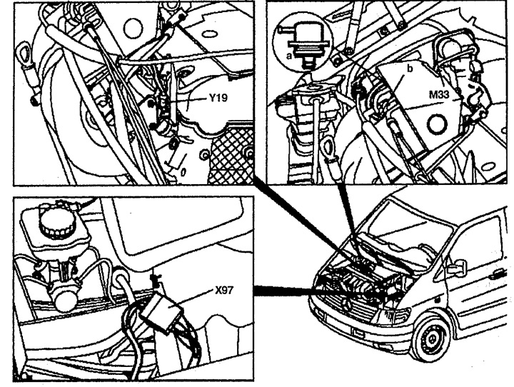
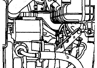
Pic. 2.113. The location of the components of the engine management system on the engine:
A. Diaphragm fuel pressure regulator,
b. vacuum tube (to diaphragm fuel pressure regulator),
MZZ. idle drive,
Y19. Nozzle,
X97. Connector 1 for engine wiring.
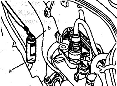
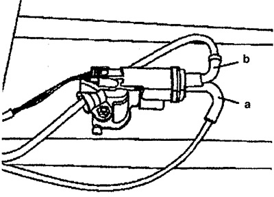
Pic. 2.114. Oxygen sensor:
A. To the oxygen sensor
b. To the engine control unit.
Pic. 2.114. Idling drive:
A. To idle drive
b. To the engine control unit.
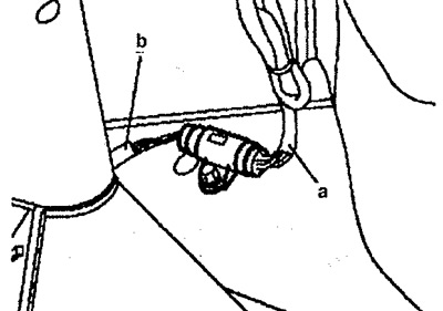
Pic. 2.116. oxygen sensor (next to the stringer):
A. To the oxygen sensor
b. To the engine control unit.
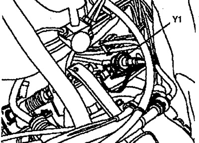
Pic. 2.117. Purge control valve Y1.
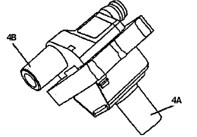
Pic. 2.118. Ignition coil:
4A. Output for spark plugs 1 and 2 cylinders,
4B. Output for spark plugs 3 and 4 cylinders.
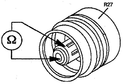
Pic. 2.119. R27 engine control unit resistor plug.
Pic. 2.120. EGR valve:
A. Vacuum tube from engine
b. Vacuum tube to recirculation valve.
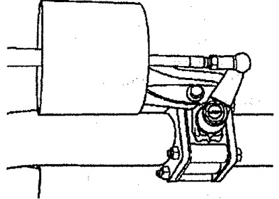
Pic. 2.121. The EGR valve is open.
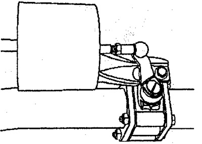
Pic. 2.122. The exhaust gas recirculation valve is closed.