
Before starting this operation, gather together all the necessary tools and materials. It is necessary that the engine be warm in order for the oil to drain better along with the bulk of the contaminants.
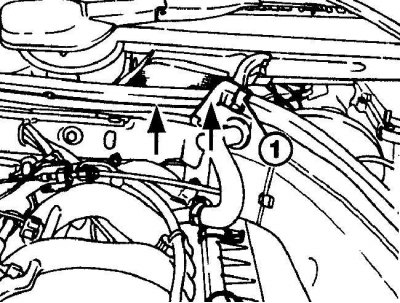
Bracket Location (1) fastening the seal to the engine compartment box
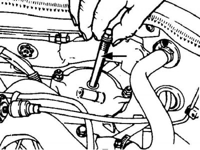
Oil return line location
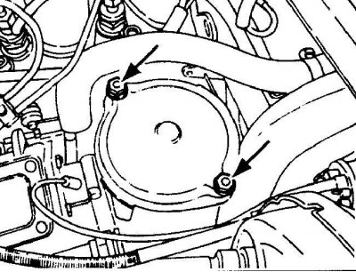
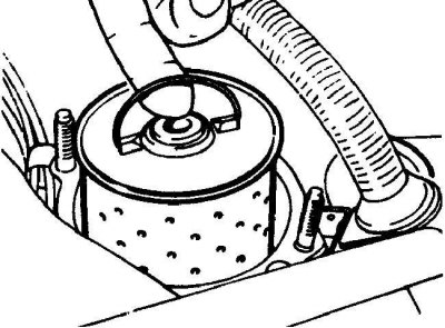
Arrangement of nuts of fastening of a cover of the oil filter
Engine oil drain plug location
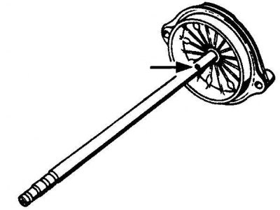
Removing the filter element from the oil filter housing
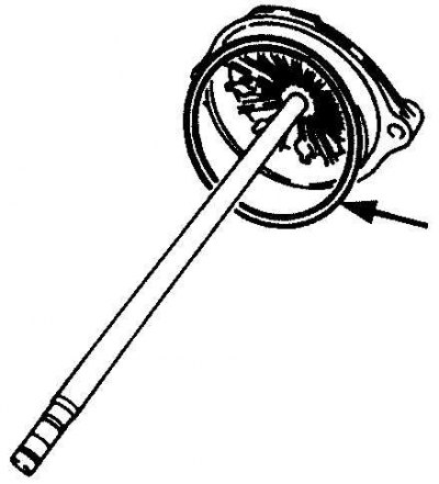
Hole at the base of the oil return line
Clean out the small hole at the base of the oil return line.
Installing a new O-ring on the oil filter cover
1. Raise the vehicle so that the engine oil drain plug is at its lowest point.
2. The oil filter housing is located in the left rear corner of the engine compartment behind the exhaust manifold.
3. If equipped, remove the mounting bracket or screw and remove the rubber seal from the top of the bulkhead to improve access to the oil filter housing (see fig. Bracket Location (1) fastening the seal to the engine compartment box).
4. On models with an oil return line attached to the center of the oil filter housing cover, unscrew the oil return line and remove it from the cover (see fig. Oil return line location).
5. Unscrew the two nuts and remove the cover from the oil filter housing (see fig. Arrangement of nuts of fastening of a cover of the oil filter).
6. Loosen the drain plug about half a turn. Place an oil drain container under the drain plug and unscrew the plug completely. If necessary, press down on the plug when unscrewing to prevent the oil from leaking prematurely. Remove the O-ring from the oil drain plug (see fig. Engine oil drain plug location).
7. When the oil is completely drained, wipe everything around the drain hole with a rag and screw the plug securely into place.
8. Remove all tools from under the vehicle and lower the vehicle.
9. Remove the filter element from the oil filter housing (see fig. Removing the filter element from the oil filter housing).
10. Wipe the casing and oil filter cover. Check the patency of the oil return pipeline. The pipeline must be free to blow. If necessary, clean the small hole at the base of the piping (see fig. Hole at the base of the oil return line).
11. Install a new O-ring to the oil filter cover (see fig. Installing a new O-ring on the oil filter cover).
12. Install a new oil filter element into the housing and cover and secure with bolts, tightening them to the required torque.
13. Install a new O-ring to the top of the oil return pipe, then install the oil return pipe.
14. Remove the dipstick to measure the oil level and remove the plug from the oil filler neck. Fill the engine with oil using the correct grade of oil. Pour in half the required amount of oil and wait a few minutes for the oil to drain into the pan. Then continue adding oil in small increments until the oil level reaches the minimum level on the dipstick. Adding about 1 liter more will bring the oil level up to the maximum level on the dipstick. Insert the dipstick to measure the oil level and close the oil filler cap.
15. Start the engine and let it run for a few minutes. Check it for oil leaks around the filter and drain plug on the oil pan. Be aware that the oil pressure warning light may stay on for several seconds as oil must fill all channels and oil reservoirs in the engine.
16. Stop the engine and wait a few minutes for the oil to drain into the sump. Check the oil level and top up if necessary.
Checking the elements of the self-levelling rear suspension system
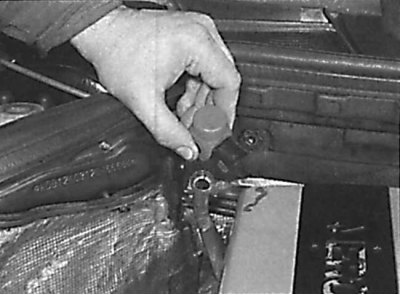
Removing the dipstick from the tank of the self-levelling rear suspension system
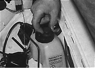
Fluid level in self-leveling rear suspension system
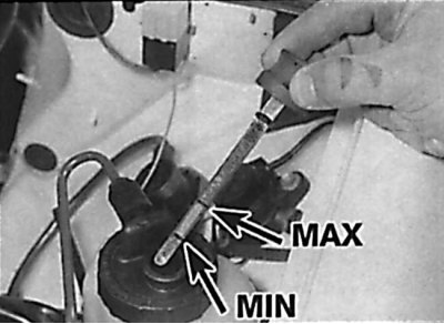
The fluid level in the self-levelling rear suspension system must be between the MIN and MAX marks on the dipstick.
Below is the procedure for performing work on models with a station wagon body.
1. Park the vehicle on a level surface and open the hood. Check the fluid level in the self leveling rear suspension system with the vehicle unloaded.
2. Remove the dipstick and use a clean rag to wipe the liquid off the dipstick. Insert a clean dipstick into the tank and remove it again. Check the fluid level, which should be between the MAX and MIN·marks on the dipstick (see fig. Removing the dipstick from the tank of the self-levelling rear suspension system, Fluid level in the self-levelling rear suspension system). If the fluid level is checked with a loaded vehicle, the fluid level may be below the MIN·mark.
3. If necessary, add the required amount of the specified fluid through the dipstick hole.
Checking the oil level in an automatic transmission
Check the oil level in the automatic transmission when the transmission is warm (oil temperature 80°C).
Removing the dipstick for measuring the oil level in an automatic transmission
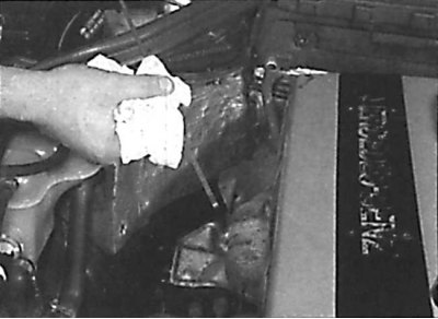
Using a rag to clean the oil dipstick in an automatic transmission
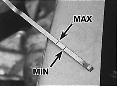
The location of the marks on the dipstick for measuring the oil level in an automatic transmission
1. Park the vehicle on a level, level ground.
2. Start the engine at idle speed and set the selector lever to position P and apply the handbrake.
3.Release the lock lever, remove the dipstick from the gearbox, wipe it clean and reinstall it (see fig. Removing the dipstick for measuring the oil level in an automatic transmission, Using a rag to wipe the dipstick for measuring the oil level in an automatic transmission).
4. Remove the dipstick and check that the oil level is between the MIN and MAX marks (see fig. The location of the marks on the dipstick for measuring the oil level in an automatic transmission).
5. If the oil level is below the MIN·mark, add oil through the dipstick hole.
6. If there is a need to add oil frequently, then it means that there is a leak that must be found and repaired as long as it does not lead to serious consequences.
Checking the tightness of the hoses and fluid leakage
1. Leaks in the cooling system are usually detected by a white or rust-colored coating in the area adjacent to the leak.
2. Carefully check the radiator and coolant hoses along the entire length. Replace hoses with cracks, tears or signs of ageing. Cracks are easier to find if the hose is pinched. Pay special attention to the clamps that attach the hoses to the elements of the cooling system. Hose clamps that have been overtightened can cause the hose to break or puncture, resulting in leaks in the cooling system. Inspect all hoses and hose connection surfaces for leaks. If any problems of this nature are found with leaks, then replace this component or gasket.
3. Fuel leaks are difficult to pinpoint until the leak is significant and therefore easily visible. Fuel tends to evaporate quickly as soon as it comes into contact with air, especially in a hot engine bay. Small drops may disappear before you can locate the leak. If you suspect that there is a fuel leak in the area of the engine compartment, then cool the engine and start it while it is cold with the hood open. Metal objects tend to shrink when cold, and rubber hoses tend to loosen, so any leaks will be more obvious while the engine is warm from start-up and cold.
4. If there are indications that some fluid is leaking, but you cannot recognize the type of fluid or the exact origin, then you should leave the car for a long time and put a large piece of paper or rag under the car. This will help locate the fluid leak and also help identify the leaking fluid by color. But keep in mind that some leaks may only show up when the engine is running.
5. A leak in the vacuum hose means that air is being sucked into the hose (does not come out of the hose), and this makes the leak very difficult to detect. The detection method is to use an old vacuum hose as a kind of stethoscope. Hold one end of the hose close to your ear (but not in the ear), and use the other end to examine the area around the suspected leak. When the end of the hose is directly over the leak, a hissing sound will be clearly audible through the hose. Contact with hot and moving parts must be avoided, as the engine must be running during the test.
Checking and replacing the auxiliary drive belt
Examination
1. With the engine off, inspect the condition of the auxiliary drive belt along its entire length. Check the accessory belt pulleys for nicks, cracks, deformation, and corrosion.
Replacement
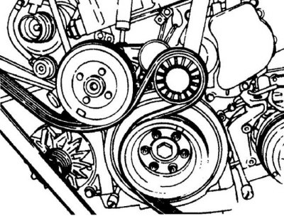
Installing the auxiliary drive belt on the idler pulley and crankshaft pulley
Elements of the auxiliary drive belt tensioner
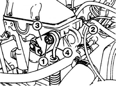
1 – a nut of fastening of the lever of the mechanism of a tension; 2 – a bolt of fastening of the lever of the mechanism of a tension; 3 - lever of the tension mechanism; 4 - spring of the lever of the tension mechanism
Moving the auxiliary drive belt between the water pump pulleys and the crankshaft
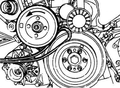
Installing the auxiliary drive belt in the pulley groove
Auxiliary drive belt location on models without air conditioning
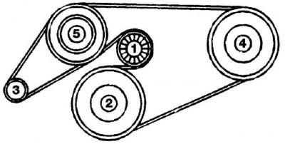
The sequence of installing the auxiliary drive belt on the pulleys:
1 - pulley of the tension mechanism; 2 - crankshaft pulley; 3 - generator pulley; 4 – a pulley of the pump of the amplifier of a steering; 5 - water pump pulley
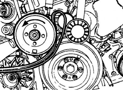
Auxiliary drive belt location on models with air conditioning system but without idler pulley
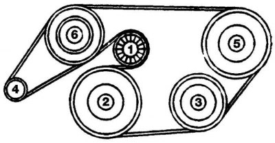
The sequence of installing the auxiliary drive belt on the pulleys:
1 - pulley of the tension mechanism; 2 - crankshaft pulley; 3 – a pulley of the compressor of an air conditioning system; 4 - generator pulley; 5 – a pulley of the pump of the amplifier of a steering; 6 - water pump pulley
Auxiliary drive belt location on models with air conditioning system and idler pulley
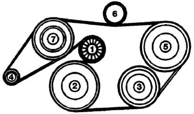
The sequence of installing the auxiliary drive belt on the pulleys:
1 - pulley of the tension mechanism; 2 - crankshaft pulley; 3 – a pulley of the compressor of an air conditioning system; 4 - generator pulley; 5 – a pulley of the pump of the amplifier of a steering; 6 - idle pulley; 7 - water pump pulley
1. Remove the fan impeller and shroud.
2. Unscrew the nut securing the tension lever (see fig. Elements of the auxiliary drive belt tensioner).
3. Insert lever (diameter 12 mm and length 300 mm) into the hole in the tensioner lever and push the lever counterclockwise just enough to move the lever bolt towards the intake manifold.
4. Turn the lever clockwise and remove the tensioner spring.
5. Move the idle pulley back and remove the auxiliary drive belt from the pulleys.
6. Install the new auxiliary drive belt as follows.
7. Raise the idler pulley slightly and hold it in this position during the following steps.
8. Squeeze the auxiliary drive belt in a loop and slide it between the water pump and crankshaft pulleys (see fig. Moving the auxiliary drive belt between the water pump pulleys and the crankshaft).
9. With your left hand, press the auxiliary drive belt into the groove of the water pump pulley and turn the water pump pulley counterclockwise and put the drive belt on the idler pulley (see fig. Installing the auxiliary drive belt in the pulley groove).
10. Install the auxiliary drive belt on the crankshaft pulley and then in the sequence shown in the figures Location of the auxiliary drive belt on models without air conditioning, Location of the auxiliary drive belt on models with air conditioning but without idler pulley, Location of the auxiliary drive belt on models with air conditioning system and idler pulley.
11. Release the idle pulley.
12. Press the tensioner lever and insert the lever mounting bolt.
13. Install the tensioner spring.
14. Secure the tensioner lever by screwing the nut onto the bolt and tightening it to the required torque.
15. Install the fan impeller and shroud.
Checking the air conditioning system
The location of the viewing window for checking the fluid level in the air conditioning system
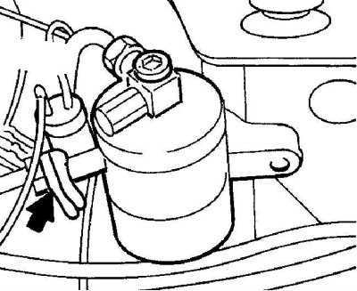
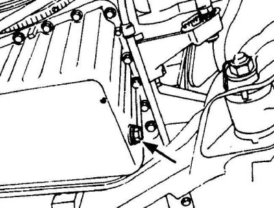
1. The air conditioning pressure sensor is located on the side of the nutrient tank.
2. Switch off the ignition and disconnect the electrical connector from the top of the pressure sensor.
3. Start the engine at idle and turn on the air conditioning system on the instrument panel.
4. Wipe the viewing window located on the side of the nutrient tank (see picture).
5. Connect the electrical connector to the pressure sensor and observe the viewing window. As a result of this, the electromagnetic clutch will turn on and the refrigerant level in the viewing window should rise. The refrigerant visible in the sight glass must be free of air bubbles.
6. If the refrigerant level in the air conditioning system is too low or the pressure in the system is too low, a pressure sensor will prevent the air conditioning system from turning on. In this case, the air conditioning system must be repaired by a specialist workshop.
Checking and adjusting idle speed
Examination
1. Check and, if necessary, adjust the accelerator cable (see subsection 9.8).
2. Start the engine and warm it up to normal operating temperature. Turn off all electrical consumers.
3. Using a diesel tachometer, check the idle speed.
Adjustment
Engines with pneumatic idle speed control
1. Loosen the jam nut on the top of the vacuum idle chamber that is attached to the back of the fuel pump.
2. By turning the vacuum chamber with a wrench, set the desired idle speed. Tighten locknut.
Engines with ELR idle speed control
1. Disconnect the electrical connector from the solenoid actuator that is attached to the rear of the fuel pump.
2. The idle speed adjustment screw is located above the housing of the electromagnetic actuator. Loosen the locknut and turn the adjusting screw to the desired idle speed. Tighten the locknut and connect the electrical connector.
Engines with EDS idle speed control
1. Disconnect the electrical connector from the solenoid actuator that is attached to the rear of the fuel pump.
2. The idle speed adjustment screw is located above the housing of the electromagnetic actuator. Loosen the locknut and turn the adjusting screw to the desired idle speed. Tighten the locknut and connect the electrical connector.
3. Idle speed can also be changed by moving a jumper in a special socket.
4. The socket is located in the accessory compartment on the rear right side of the engine compartment.
5. To change the position of the jumper, remove it from the socket and install it in a new position, which is indicated by numbers from 1 to 7 on the back of the socket.
6. Position #1 corresponds to 600 rpm and position #7 corresponds to 700 rpm.
Checking the front suspension and steering
Front wheel hub bearing wear check
1. Raise the front of the vehicle and secure it on stands.
2. Visually inspect the ball joint dust boot and rack and pinion boot for cracks, abrasions and ageing. Any wear on these boots will result in loss of lubricant and ingress of water and dirt, resulting in rapid wear of the ball joints or steering gear.
3. Check the power steering gear hoses for chafing or aging, and pipes and hose connections for leaks. Also check for signs of a pressure leak in the protective rubber boots of the steering gear, which indicate damage to the steering seal.
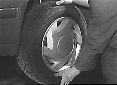
4. Raise the car with a jack, take the wheel with your hands at the 6 and 12 o'clock positions and try to shake it in a vertical plane. Very little wheel play is acceptable, but if the play is large enough, further testing is needed to establish the source. Continue pumping the wheel while the assistant applies the foot brake. If the play is eliminated or significantly reduced, it is likely that the hub bearings are damaged. If the play is still significant with the brake applied, then there is wear in the connection and suspension mount (see picture).
5. Now take the wheel to the 9 and 3 o'clock position and try to shake it in a horizontal plane. The presence of play in the horizontal plane can be caused by wear of the hub bearing or tie rod ball joints. If the outer or inner ball joint is worn, play will be evident.
6. Using a large screwdriver as a lever, check for wear in the suspension mount bushings between the suspension element and the application point. Some movement should be visible as the mount bushings are made of rubber, but excessive wear should be evident. Also check the condition of any visible parts of the rubber bushings for cracks, wear and deformation.
Shock absorber check
Check the shock absorber for any signs of fluid leaks. If a leak is found, then the shock absorber is damaged and needs to be replaced.
Attention! Shock absorbers must be changed in pairs on the same axle.
The effectiveness of the shock absorber is also tested by pressing on the corner of the body and releasing it abruptly. The body should return to its original position after it is released. If the body rises above its original position and continues to sway, it is likely that the shock absorber located on this side is out of order and must be replaced. Also check the shock absorber mount for wear.
Checking the protective cover of the drive shaft
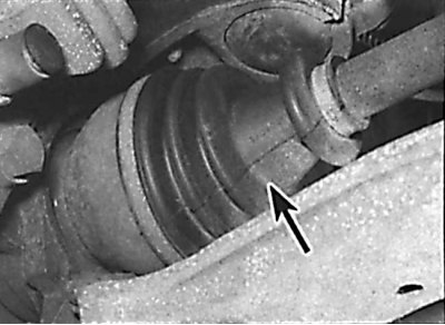
Check of a condition of a protective cover of the hinge of equal angular speeds of a driving shaft
1. Raise the rear of the car and secure it on stands.
2. While rotating the rear wheel, inspect the CV joint rubber boots, squeezing them to open the folds. Check them for cracks, which can lead to grease leakage, as well as water and dirt ingress (see picture).
3. Also check the condition of the mounting clamps, inspect the covers of the internal hinges and casings on the other side. If any damage is found, the protective cover must be replaced immediately.
4. At the same time, check the general condition of the CV joints by holding the shaft while trying to turn the wheels. Try again, holding the inner CV joint and rotating the shaft. Any noticeable play indicates wear on the pivot, wear in the shaft slots, or a loose shaft lock nut.
Checking the front brake pads
1. Apply the handbrake, raise the front of the vehicle and support it on stands. Remove the front wheels.
2. Check the thickness of the brake pads through the inspection hole in the front of the caliper.
3. If the brake pad is worn to the minimum thickness, all four brake pads must be replaced as a set.
4. Install wheels and lower vehicle.
Checking the rear brake pads
1. Raise the rear of the car and secure it on stands. Remove rear wheels.
2. Inspection of the brake pads can be done through the inspection hole at the top of the rear caliper. If the brake lining is worn to the minimum thickness, all brake pads in the set must be replaced.
3. Install wheels and lower vehicle.
Exhaust system check
1. On a cold engine, check the condition of the exhaust system along its entire length.
2. Check pipes and their connections for leaks, signs of corrosion and damage. Check that all brackets and suspension elements of the exhaust system are in good condition and evenly tensioned.
3. When moving the exhaust system of the car to the sides, check that it does not touch the car body. If not, replace the exhaust rubber mounts.
Checking the oil level in a manual transmission
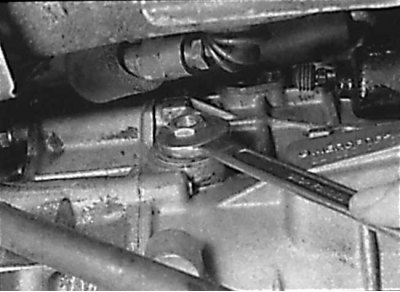
Unscrewing the oil level plug in a manual transmission
1. Install the car in a horizontal position above the inspection hole. Check the oil level no earlier than 5 minutes after stopping the engine.
2. Clean the area around the transmission oil level plug. The oil level plug is located on the front right side of the transmission. Unscrew the plug and clean it (see picture).
3. The oil level should reach the lower edge of the oil level plug hole.
4. If necessary, add oil to the gearbox through the oil level plug hole.
5. Screw in the oil level plug in the gearbox to the required torque.
Checking the oil level in the main reverse gear
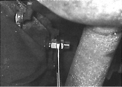
Unscrewing the plug for checking the oil level in the main reverse gear
1. Place the car over a viewing hole or raise it on a lift.
2. Clean the area around the oil level plug located on the left front side of the final reverse gear. Unscrew the stopper (see picture).
3. The oil level should reach the lower edge of the oil level check hole.
4. If necessary, add oil to the gearbox through the oil level plug hole.
5. Screw the oil level plug into the final reverse gear and tighten to the specified torque.
6. Lower the car.