



Front direction indicator
1. When working on the right unit, disconnect the wires from the washer fluid level indicator sensor, remove the nut on the large plastic cover and move the reservoir slightly to improve access.
2. Disconnect the wires from the back of the lamp holder.
3. Loosen the knurled fastening nut (see fig. 13.3) and pull the lantern forward.
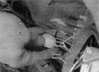
Fig. 13.3. Unscrew the knurled nut of the turn signal
4. Installation is carried out in the reverse order, while aligning the two tabs with the guides in the headlight unit (see fig. 13.4).
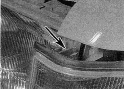
Fig. 13.4. Upper direction indicator mounting tab (shown by arrow)
Headlight unit
5. Remove the turn signal as described previously.
6. Disconnect the vacuum hose and the multi-pin connector wire from the rear of the headlight assembly (see Fig. 13.6, a, b).
(Material borrowed from an online resource: www.mercedesman.ru)
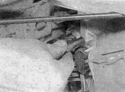
Fig. 13.6, a. Disconnect the vacuum hose of the headlight unit...
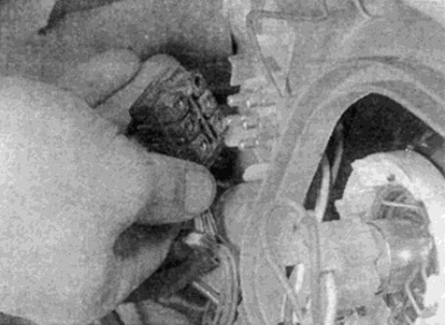
Fig. 13.6, b....and multi-pin connector
7. Loosen the inner end mounting bolt, then separate the outer end of the decorative belt by moving it towards the center of the car (see Fig. 13.7, a, b). Remove the belt.
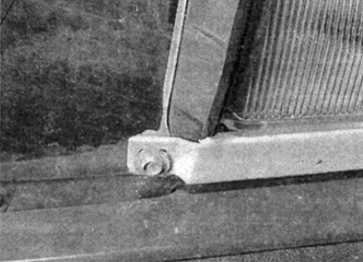
Fig. 13.7, a. Unscrew the decorative belt mounting bolt...
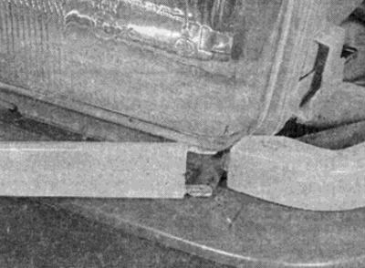
Fig. 13.7, b....and separate the outer end of the belt
8. Unscrew the two upper mounting bolts and the lower bolt (see fig. 13.6), then remove the node.
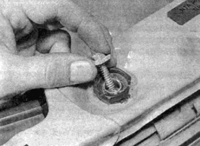
Fig. 13.8, a. Unscrew the upper mounting bolts...
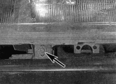
Fig. 13.8, b....and one lower bolt (shown by arrow)
9. Installation is carried out in the reverse order. Before installing the lower mounting screw, align the tabs of the lower mounting with the groove on the body panel (see fig. 13.9). Initially tighten the fasteners by hand and make small adjustments to the position of the unit, if necessary, by turning the upper fastening nut. After the position of the headlight is set, tighten the fasteners securely.
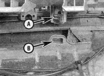
Fig. 13.9. When installing, align the lower tab (A) with the groove (B)
Rear lights
10. From the luggage compartment, turn the two lock handles to the left as far as possible and remove the bulb holder from the lamp unit.
11. Disconnect the multi-pin connector, then unscrew the six nuts securing the light assembly (see Fig. 13.11, a, b).
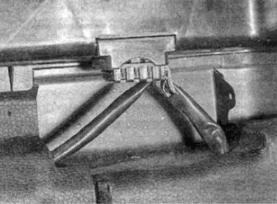
Fig. 13.11, a. Disconnect the multi-pin connector of the rear light unit...
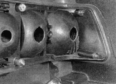
Fig. 13.11, b....unscrew six nuts...
12. Press the two fasteners and remove the unit from the outside of the vehicle (see Fig. 13.12, a, b).
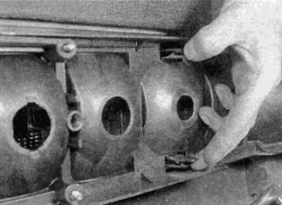
Fig. 13.12, a....press the two clamps...
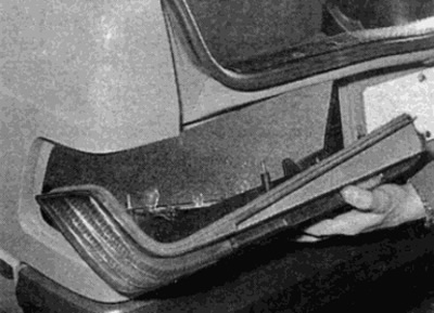
Fig. 13.12, b....and remove the light assembly
13. Installation is carried out in reverse order.