
Release models prior to January 1985
Removing
1. Disconnect the negative battery terminal.
2. Remove the wiper arm as previously described.
3. Pry off the cover from above on the axis of rotation of the wiper arm.
4. Remove the two clips, one on each side at the front, securing the air inlet cover over the air box.
5. Remove the rubber seal to release the front of the cover.
6. Remove the rear seal on both sides, then remove the two screws, one on each side, securing the cover to the bulkhead of the engine compartment.
7. Remove the air intake cover from the air box.
8. Remove the three rear and one front bolts securing the motor and linkage to the bulkhead of the engine compartment.
9. Remove the cover above the central mounting block (fuses) and remove the two mounting nuts and two screws.
10. Remove the main mounting block up and forward, then disconnect the wiper motor wire block from the base of the block.
11. Manipulate to remove the motor and linkage.
Installation
12. Installation is carried out in the reverse order.
Models released after January 1985
Removing
13. Remove the panoramic wiper arm. as described in the previous paragraph.
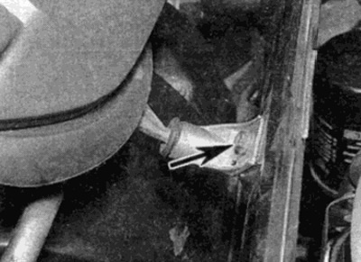
14. Remove the two screws and retainers, one on each side at the front, securing the air intake grille to the top of the air intake plenum (see fig. 18.14).
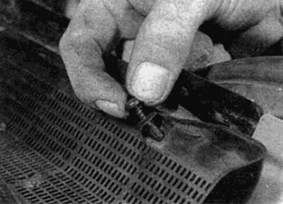
Pic. 18.14. Loosen the front screws of the air intake cover
15. Remove the rubber seal from the front of the cover (see fig. 18.15).
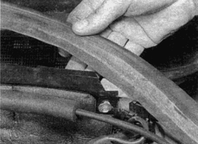
Pic. 18.15. Lift rubber seal
16. Remove the rear seal on both sides, then remove the two screws, one on each side, securing the air intake cover to the bulkhead of the engine compartment (see fig. 18.16).
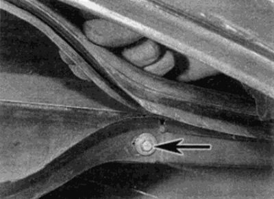
Pic. 18.16. Remove the rear seal and remove the screw (shown by arrow) at both sides
17. Remove the air intake cover from the air intake box (see fig. 18.17).
Pic. 18.17. Remove the air intake cover
18. Remove the bolt and pull the front support bracket off the linkage stud (see fig. 18.18, a, b).
Pic. 18.18, a. Remove the bolt (shown by arrow)...
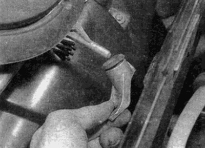
Pic. 18.18, b....and remove the support bracket
19. Unscrew the bolts securing the lever mechanism to the bulkhead of the engine compartment and remove it forward into the air intake box (see fig. 18.19).
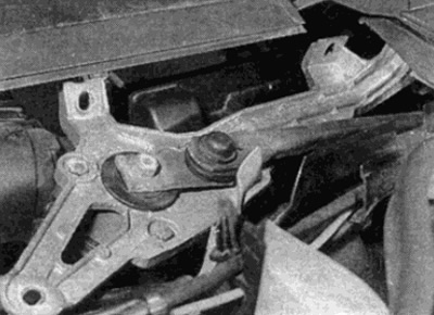
Pic. 18.19. Pull the linkage into the air box
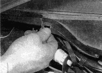
20. Disconnect the motor wiring harness and remove the assembly from the vehicle (see fig. 18.20, a, b).
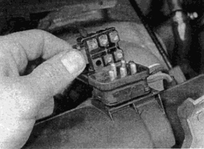
Pic. 18.20 a.m. Disconnect the motor connector...
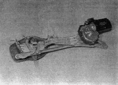
Pic. 18.20 b....and remove the motor and linkage
Installation
21. Installation is carried out in the reverse order.