
Illumination lamps and control lamps
2. Turn the lamp holders counterclockwise and remove them from behind the instrument panel (see fig. 9.2).
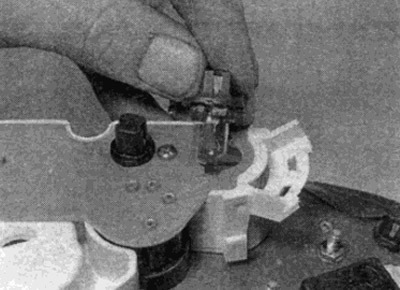
Pic. 9.2. Replacing the instrument panel illumination lamp
3. Remove the backlight by pulling it out of the holder. Pilot lamps (except for the generator control lamp) are replaced with holders.
4. Install the lamp holders by pushing them down and turning them clockwise.
Speedometer
5. Remove the resistance block on the back of the speedometer by pulling it up (see fig. 9.5). The block is fixed with two screws, unscrew them first.
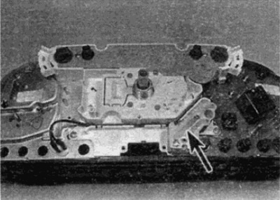
Pic. 9.5. The location of the resistance unit on the instrument panel (shown by arrow)
6. Remove the four screws securing the speedometer to the rear of the instrument panel.
7. Remove the two screws or loosen the latches and pull out the bulb holder above the speedometer.
8. Where provided, remove the coolant level indicator pump and release the wiring next to the speedometer.
9. Remove the speedometer from the instrument panel.
10. Installation is carried out in the reverse order.
Tachometer
11. Remove the speedometer as described above.
12. Remove two additional screws (see fig. 9.12) and remove the block.
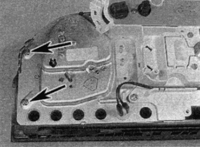
Pic. 9.12. Tachometer mounting screws (shown by arrows)
13. Installation is carried out in the reverse order.
Block of pointer devices
14. Remove a speedometer as it is described earlier.
15. Remove two additional screws (see fig. 9.15) and remove the instrument cluster.
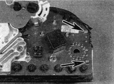
Pic. 9.15. Screws of fastening of the block of devices (shown by arrows)
16. Installation is carried out in the reverse order.