
Headlights
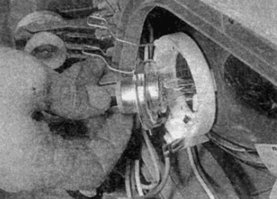
1. Working from the engine compartment, unfasten the two lamp cover latches, tilt the cover back and lift it up (see fig. 11.1, a, b).
Pic. 11.1, a. Unfasten the latches on the headlight bulb cover...
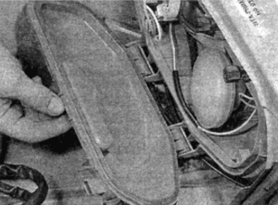
Pic. 11.1, b....and remove the lid
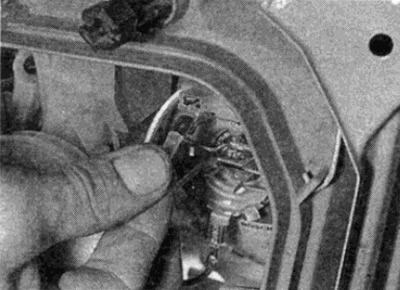
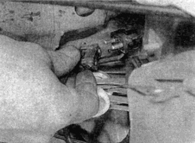
2. Disconnect the wire plug (see fig. 11.2, a, b) and release the lamp retainer by squeezing the retainer folders together and swinging them outward.
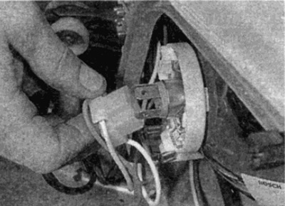
Pic. 11.2, a. Disconnect the wire harness...
Pic. 11.2, b... and release the headlight bulb retainer...
3. Remove the lamps from the optical element (see fig. 11.3). Do not touch the lamp bulb with your fingers.
Pic. 11.3....then pull out the lamp
4. Installation is carried out in reverse order, but make sure that the tips on the pump plate are aligned with the recesses in the lamp unit.
Advice. If you touch the bulb of the lamp, wipe its surface with a cloth moistened with ethyl alcohol.
Side light lamps
5. Remove the cover of the headlight unit, as described in paragraph 1.
6. Remove the marker lamp holder located under the headlight lamp.
7. Remove the bulb by turning it counterclockwise.
8. Install 8 in reverse order.
Fog lights
9. Remove the cover of the headlight unit, as described in paragraph 1.
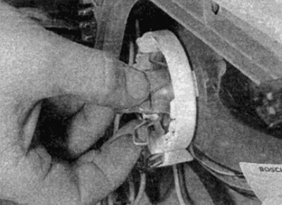
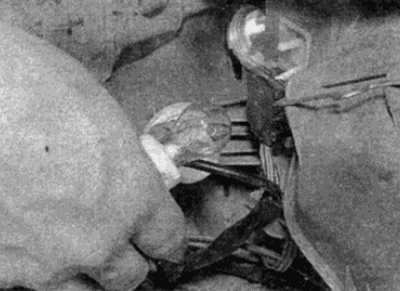
10. Disconnect the electric wire of the pump at the connector (see fig. 11.10).
Pic. 11.10. Disconnect the electrical wire from the fog lamp
11. Squeeze the latch and pull it out (see fig. 11.11).
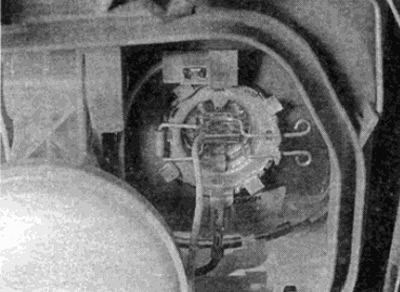
Pic. 11.11. Loosen the retainer to remove the fog light bulb
12. Remove the pump from the optical element without touching the lamp bulb. Wipe the flask with a cloth soaked in ethyl alcohol if you touch the flask.
13. Installation is carried out in the reverse order.
Front direction indicators
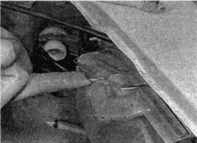
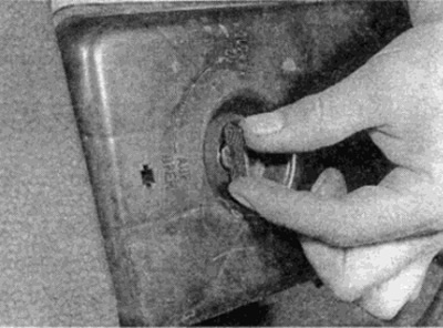
14. When working with the right lamp, disconnect the wires from the sensor of the liquid level indicator in the washer reservoir, unscrew the large nut of the plastic cover (see fig. 11.14) and move the tank to provide access to the lamp.
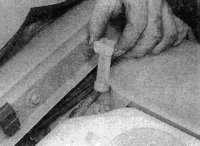
Pic. 11.14. Removing the washer reservoir cap nut
15. Disconnect the wires from the lamp holder, then turn the holder counterclockwise (see fig. 11.15, a, b).
Pic. 11.15 a.m. Disconnect the turn signal lamp wires...
Pic. 11.15 b....and remove the lamp holder
16. Turn the lamp counterclockwise to remove it from the holder.
17. Installation is carried out in the reverse order.
Turn signal repeater
18. Gently pry the side turn signal lens out of the body side panel using a screwdriver inserted into the front edge of the assembly.
19. Pull the lamp holder out of the assembly and remove the lamp from the holder (see fig. 11.19).
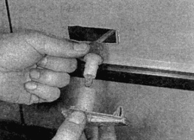
Pic. 11.19. Replacement of a lamp of the lateral repeater of the index of turns
20. Installation is carried out in the reverse order.
Tail lamps
21. Operating from the luggage compartment, turn the two lock handles to the left as far as possible and remove the lamp holder from the lamp unit (see fig. 11.21, a, b).
Pic. 11.21 a. Loosen the lock knob...
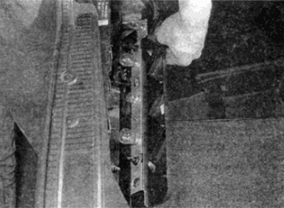
Pic. 11.21 b....and remove the rear light bulb holder
22. Remove the appropriate pampa by turning it counterclockwise (see fig. 11.22). Lamp numbers and their power are indicated next to the lamps.
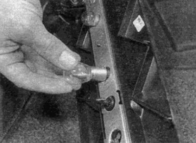
Pic. 11.22. Remove the corresponding lamp from the holder
23. Installation is carried out in the reverse order.
License plate lamp
24. Remove the two mounting bolts and remove the assembly lenses (see fig. 11.24. a, b).
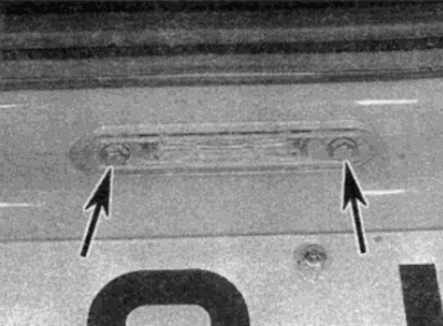
Pic. 11.24 a. Loosen the two fixing screws (shown by arrows)...
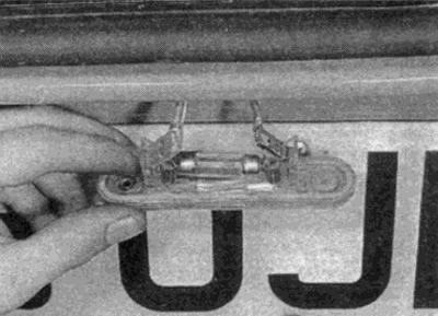
Pic. 11.24 b....and remove the license plate light
25. Wring out contacts and remove a finger lamp.
26. Installation is carried out in the reverse order.