
Cars BMW Cars Volkswagen Cars Chevrolet Cars Land Rover Cars Lada Cars Honda Cars Peugeot
English Русский
Български
Беларускі
Український
Српски
Hrvatski
Română
Polski
Slovenský
Magyar
Bookmark News and articles Sitemap Feedback Site search
MercedesMan.ru


A-Class C-Class E-Class G-Class M-Class S-Class Others
Sprinter (1995-2000, diesel) Vito 1 (1996-2003) Vito 2 (2003-2014, diesel) Vario 814D (1996-2003, diesel)
  • Main
  • Mercedes-Benz
  • Vito 1 (1996-2003)
  • Chassis
  • Brake system
  • ABS/ABD system component locations, ABS/ABD system schematic diagram and ABS/ABD control unit wiring connector image

ABS/ABD system component locations, ABS/ABD system schematic diagram and ABS/ABD control unit wiring connector image (Mercedes-Benz Vito W638)

0
The location of the ABS/ABD system components, the basic diagram of the ABS/ABD system and the image of the ABS/ABD control unit wiring connector are shown in the figure 9.16 - 9.24.

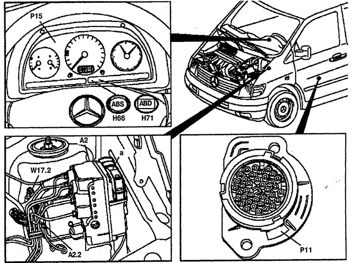
Figure 9.16. Location of ABS/ABD system components:

Figure 9.16. Location of ABS/ABD system components:
a. 40-pin ABS/ABD control unit wiring connector,
A2. Hydraulic unit with ABS/ABD control unit,
A2.2. Connection to ground of the return pump,
H66. ABS/ABD Malfunction Indicator Lamp (MIL),
H71. ABD/ETS system malfunction indicator lamps,
P11. 38-pin wiring connector (under the driver's seat),
P15. Instrument cluster,
W17.2. Ground connection on the left in the engine compartment.
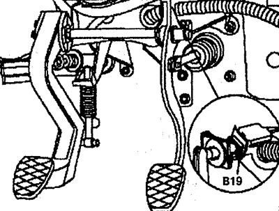

Figure 9.17. Location of ABS/ABD system components:

Figure 9.17. Location of ABS/ABD system components:
B19. Brake light switch.
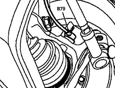

Figure 9.18. Location of ABS/ABD system components:

Figure 9.18. Location of ABS/ABD system components:
B79. Front wheel speed sensor.
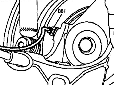

Figure 9.19. Location of ABS/ABD system components:

Figure 9.19. Location of ABS/ABD system components:
B81. Rear wheel speed sensor.
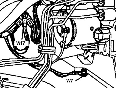

Figure 9.22. Location of ABS/ABD system components:

Figure 9.22. Location of ABS/ABD system components:
W7. Ground connection on the left in the engine compartment (under the hydraulic block).
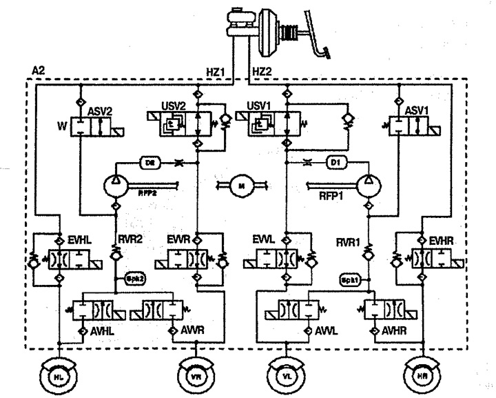

Figure 9.23. Functional diagram of the ABS/ABD system:

Figure 9.23. Functional diagram of the ABS/ABD system:
A2. Hydraulic unit with built-in control unit,
ASV. Intake valve (ABD/ETS),
AVHL. Rear left exhaust valve,
AVHR. Rear right exhaust valve,
AWL. Front left exhaust valve,
AWL. Front right exhaust valve,
D. Damper chamber,
EVHL. Rear left intake valve,
EVHR. Rear right intake valve,
EWL. Front left intake valve,
EWR. Front Right Inlet Valve,
HZ. Master brake cylinder,
HL. Left rear wheel,
HR. Right rear wheel,
M. Return pump drive,
RFP. Return pump,
RVR. Pressure Reducing Valve,
SPK. Reservoir,
USV. Switching valve,
VL. Front left wheel,
VR. Front right wheel.
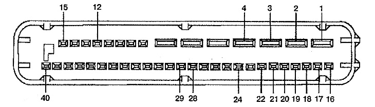

Figure 9.24. ABS/ABD control unit wiring connector:

Figure 9.24. ABS/ABD control unit wiring connector:
1. 15. Ground connection,
2. Positive battery pole (fuse F6 50A),
3. Positive battery pole (fuse F7 25A),
4. Terminal 15 of the ignition system (fuse F5 105A),
12. ABD/ETS system malfunction indicator lamp,
16. Positive pole of the front left wheel speed sensor,
17. Ground connection of the front left wheel speed sensor,
18. Positive pole of rear left wheel speed sensor,
19. Ground connection of the rear left wheel speed sensor,
20. Positive pole of rear right wheel speed sensor,
21. Ground connection of the rear right wheel speed sensor,
22. Positive pole of the front right wheel speed sensor,
24. Ground connection of the front right wheel speed sensor,
28. Brake light switch,
29. Diagnostic connector.
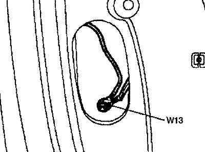

Figure 9.20. Location of ABS/ABD system components:

Figure 9.20. Location of ABS/ABD system components:
W13. Ground connection in the rack.
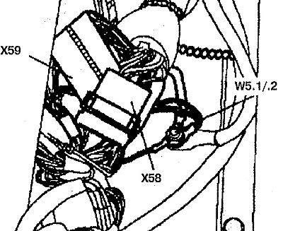

Figure 9.21. Location of ABS/ABD system components:

Figure 9.21. Location of ABS/ABD system components:
X58, X59. Wiring connectors,
W5.1/2. Ground connection on driver's seat frame.
This article is available at: russian, bulgarian, belarusian, ukrainian, serbian, croatian, romanian, polish, slovak, hungarian
The article has been verified: Lukyanov Nikita Ilyich
Share with friends:
◀ Previous
Mercedes Vito 1 / Brake system
Next ▶

Rear parking brake cables
Front parking brake cable
Adjusting the parking brake system
Brake pads of the parking brake system
Parking brake drive mechanism
Hydraulic unit ABS/ABD or ABD/ETS
ABS Wheel Speed Sensors
Tightening torque of brake system components
More similar articles for repairing other models

☛ General description of the braking system Mercedes W168 (1997-2004)
☛ Anti-lock braking system (ABS) wiring diagram Mercedes W203 (2000-2007)
☛ Diagram 13. Adaptive suspension control system (ADS) Mercedes W210 (1996-2002)
☛ The operating principle of the control and injection system of a… Mercedes W463 (1999-2019)
☛ Automated air conditioning system (climate control) Mercedes W163 (1997-2005)
☛ ME-SFI Fuel Injection and Ignition Control System Component Locations Mercedes W140 (1991-1998)
Link in different formats to this article
Comments and feedback from visitors
Евгений (30.10.2025 17:06)
спасибо очень помогли и доступно
ответить цитировать


How much will 46 + 13 ?


Vario 814D (1996-2003, diesel) 
  • General information
  • Maintenance
  • Power unit
  • Engines 602.984/985
  • Engines 904.908/914/923/936
  • Transmission
  • Clutch
  • Manual gearbox 711.613
  • Manual gearbox 710.64/66
  • Manual gearbox 715.051
  • Automatic gearbox 723.345
  • Power take-off box
  • Chassis
  • Front suspension
  • Rear suspension
  • Steering
  • Brake system
  • Body and electrical equipment
  • Interior (internal elements)
  • Exterior (external elements)
  • Heater and air conditioner
  • Electrical diagrams
Vito 2 (2003-2014, diesel) 
  • General information
  • User manual
  • Maintenance
  • Diesel engine OM646
  • Engine repair
  • Cooling and lubrication system
  • Power and exhaust system
  • Transmission
  • Clutch
  • Car gearbox
  • Chassis
  • Front suspension
  • Rear suspension
  • Steering
  • Brake system
  • Body
  • Body elements
  • Electrical equipment
  • Equipment and devices
  • Security systems
  • Electrical circuits
Vito 1 (1996-2003) 
  • General information
  • User manual
  • Maintenance
  • Petrol engines 2.0 l
  • Engine repair
  • Lubrication system
  • Cooling system
  • Power and control system
  • Petrol engines 2.8 l
  • Engine repair
  • Lubrication system
  • Cooling system
  • Power and control system
  • Diesel engines 2.3 l
  • Engine repair
  • Cooling system
  • Lubrication system
  • Turbocharging and recycling
  • Power and control system
  • Diesel engines 2.2 l
  • Engine repair
  • Cooling system
  • Lubrication system
  • Turbocharging and recycling
  • Power and control system
  • Transmission
  • Clutch
  • Mechanical gearbox
  • Automatic gearbox
  • Chassis
  • Front suspension and wheels
  • Rear suspension
  • Steering
  • Brake system
  • Body
  • Exterior (external elements)
  • Interior (internal elements)
  • Electrical equipment
  • Equipment and devices
  • Heater and air conditioner
  • Electrical circuits
Sprinter (1995-2000, diesel) 
  • General information
  • Introduction to the guide
  • Maintenance
  • Power unit
  • Engine repair
  • Lubrication system
  • Cooling system
  • Power and exhaust system
  • Transmission
  • Clutch
  • Mechanical gearbox
  • Automatic gearbox
  • Front axle
  • Rear axle and cardan
  • Chassis
  • Car suspension
  • Steering
  • Brake system
  • Tires and wheels
  • Electrical equipment
  • Equipment and devices
  • Headlights and lighting
  • Power devices
  • Electrical circuits
 
MercedesMan.ru © 2017–2026 · Mobile version · Read about Mercedes · Sitemap: EN BG BY UA RS HR RO PL SK HU · Feedback · Site search · Bookmark A-Class (W168) · C-Class (W201) · C-Class (W202) · C-Class (W203) · E-Class (W123) · E-Class (W124) · E-Class (W210) · G-Class (W463) · M-Class (W163) · S-Class (W116, petrol) · S-Class (W126, petrol) · S-Class (W140) · S-Class (W220) · Sprinter · Vito 1 · Vito 2 · Vario 814D ·
 
We only use cookies without which some of the site's features may not be available.