



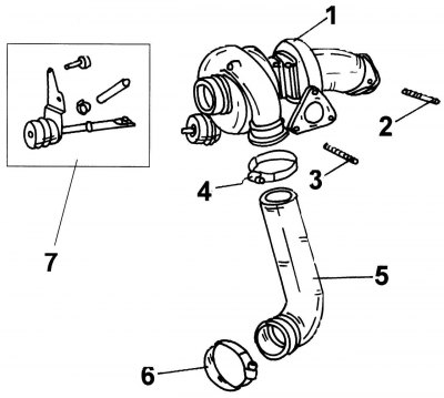
Figure 170. Turbocharger: 1 - turbocharger; 2, 3 - studs; 4 — pipe mounting clamp; 5 - connecting hose; 6 — clamp; 7 - vacuum valve
The appearance and mounting of the turbocharger are shown in the figure 170. If it needs to be removed, you should first dismantle the parts blocking access, and then unscrew the compressor from the fasteners shown in the figure.
Installation is carried out in the reverse order, observing the tightening torques of the threaded connections. Some key points that should also be taken into account are given in the text above.
Tightening torques for connections, Nm:
- turbocharger to wastegate valve 21
- oil lines to turbocharger 22
- oil line to cylinder block 30
- return oil line to turbocharger and cylinder block 9
- turbocharger mounting bolts 11