
Engine cooling system
All models of vehicles discussed in this manual are equipped with a positive pressure engine cooling system with thermostatically controlled circulation of the working fluid. The water pump is fixed on the engine block and provides pumping of the coolant through the cooling path of the latter. The flow of fluid washes the areas where each of the cylinders in the block is located, after which it is directed to the rear of the engine. Cast-in-the-block and cylinder-head cooling ducts provide intensive cooling for intake and exhaust ports, spark plug areas and exhaust valve guides.
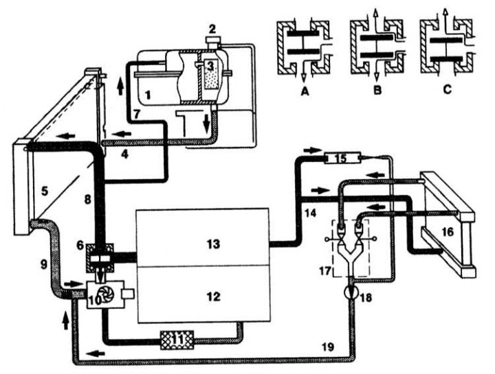
The general scheme of the functioning of the cooling system
1 - Expansion tank; 2 - Cover; 3 - Built-in silica gel tank; 4 - Intake pipe; 5 - Radiator; 6 - Thermostat; 7 - Ventilation tube; 8 - Flow from the engine to the radiator; 9 - Flow from the radiator to the engine; 10 - Pump of the cooling system; 11 - Oil cooler; 12 - Cylinder block; 13 - Cylinder head; 14 - Heater delivery pipeline; 15 - Windshield washer heater; 16 - Heater radiator; 17 - Double pulsation valve; 18 - Circulation pump; 19 - Heater return pipe
From the moment the engine is started, the cooling system goes through three modes of operation: at the first stage, until the temperature of the coolant has risen above a certain value, it circulates in a small circle from the working circuit of which the radiator is excluded. As the liquid warms up further, the poppet valve of the wax-filled thermostat entering the system path opens and a radiator is connected to the circulation circuit. Further, when the temperature of the coolant reaches the next control value, a temperature-sensitive sensor-switch is activated, which activates the fan of the cooling system, which pumps additional air flow, which greatly increases the efficiency of the radiator heat exchanger.
The cooling system is hermetically sealed and tightly sealed with a radiator cap capable of withstanding a certain overpressure, which increases the boiling point of the coolant and, accordingly, the efficiency of heat removal through the radiator. When the internal pressure in the system exceeds a certain value, an excess of coolant flows through the connecting (overflow) tube into the expansion tank. As the system cools down, the fluid automatically returns from the reservoir to the radiator.
Coolant is added to the system through the expansion tank neck (see chapter Current service) which at the same time also acts as a receiver, accumulating the excess liquid displaced from the radiator.
In view of the above design features, such a cooling system is called closed, since it excludes any functional loss of the working fluid.
Heating and ventilation system
The heating system consists of fans and heat exchangers located in the blocks of the front and rear parts of the cabin. The hot coolant flows through the heat exchangers. When moving the heater mode control handle located on the control panel (see more details. Comfort Chapters Manual) valves open and hot air begins to flow into the interior of the car. If you turn on the heater fan, air will be forced into the passenger compartment.
Outside air passes through a filter before entering the cabin (contact the head Current service). The bulk of the dust particles will settle in the filter. The filter replacement interval must be observed. A filter blocked by dust will restrict the air supply to the passenger compartment, resulting in air stagnation inside the passenger compartment.
The distribution of air flows of the ventilation system is carried out with the help of dampers. The mode of air circulation is provided. The flaps are controlled by servo drives.
Independent heater
The standard equipment of some models may include an independent heater, which provides the possibility of autonomous heating of the engine and car interior by a timer signal or from the remote control. The principle of operation of an independent heater is considered in Section Independent heater Chapters Manual.