
General information
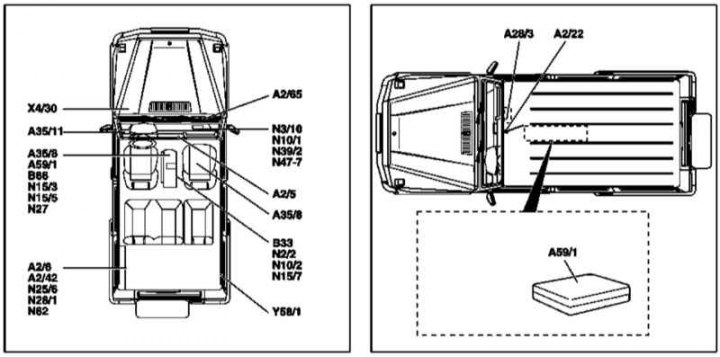
The layout of the control modules on board the vehicle
А2/5 - Antenna divider; A2 / 6 - CD changer; A2/22 - Antenna; А2/42 - TV tuner; A2/65 - Antenna amplifier; A35/8 - Emergency call system control module (E-call) TELE AID; A35 / 11 - Control module of the Linguatronic system; B33 - Anti-theft tilt sensor (ATA); B66 - Cone tilt sensor; N2/2 - SRS control module; N3/10 - ME-SFI injection control module; N10/1 - Right SAM control module/mounting block; N10/2 - Rear SAM control module/mounting block; N15/3 - AT control module (TCM/ETC); N15/5 - Selector module (ESM) AT; N15/7 - VGS transfer case control module; N25/6 - Rear seat heating control module; N27 - Towing protection sensor control module; N28/1 - Control module of the trailer connection registration system; N39/2 - CDI injection control module; N47-7 - ABS control module; N62 - Reversing assistance system control module (BA); X4/30 - Terminal block (circuit 30 engine); Y58/1 - Canister purge valve
Description of procedures for removing and installing injection control modules (ME-SFI/CDI), AT (TCM/ETC), transfer box, brake and auxiliary stabilization systems (ABS/BAS/EBV/ESP) given in the relevant Chapters of the Manual (see chapters Power supply and exhaust systems, automatic transmission, transmission line and Suspension and steering).
COMAND system control module with multifunction display (code ET4)
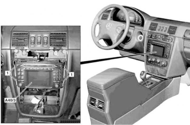
Installation details of the COMAND control module with multifunction display (1 of 2)
1 - Bolt
A40 / 3 - Command control module with multifunction display
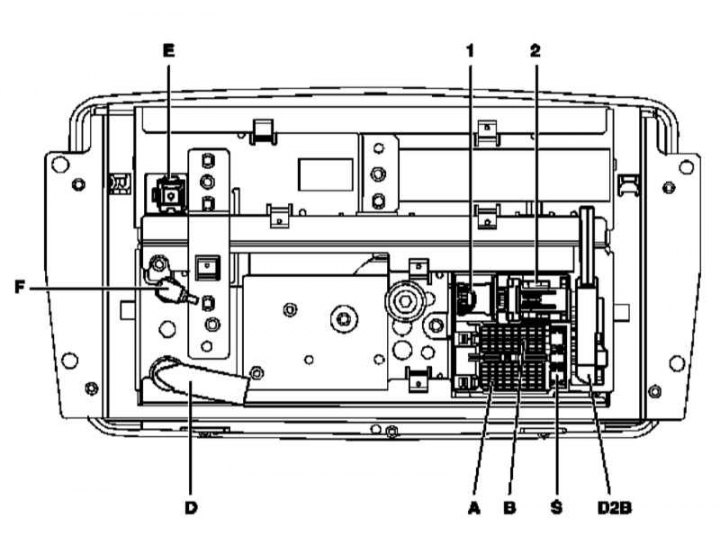
Installation details of the COMAND control module with multifunction display (2 of 2)
1 - RGB TV tuner signal connector; 2 - CAN bus connector (to instrument cluster); A - Power supply connector; B - Loudspeaker connector; D2B - Fiber optic bus connector; D - FM/AM antenna input connector; E - GPS input connector; F - IF* output connector; S - Fuse
1. On models of the corresponding configuration (code ET2) activate the service mode of the TELE AID emergency call system (see Section Activation / deactivation of the service mode of the TELE AID emergency call system).
2. Disconnect the negative cable from the battery.
3. Remove facing of the central section of the panel of devices (see Removal and installation of the facing panel of the console section of the instrument panel).
4. Turn out fixing bolts (1) and release the control module/multifunction display assembly (A40/3) from the instrument panel.
5. Disconnect electrical connectors (1, 2, A, B, D, E, F).
6. Carefully, being careful not to pull or pinch the cable, disconnect the fiber optic D2B connector.
7. Installation is carried out in the reverse order, - with the appropriate configuration (code ET2) deactivate the service mode of the TELE AID system (see Section Activation / deactivation of the service mode of the TELE AID emergency call system).
8. Finally, read the DTCs and clear the OBD memory using the STAR DIAGNOSIS scanner (6511 1801 00) (see chapter Engine Electrical Systems).
Door assembly control modules
Front door
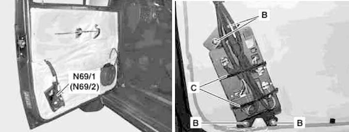
Front Door Control Module Installation Details
B - Mounting screws; C - Strappings; N69/1 - Left door control module; N69/2 - Right door control module
1. Turn on the auxiliary battery and connect it to the standard battery, then disconnect the negative cable from the latter.

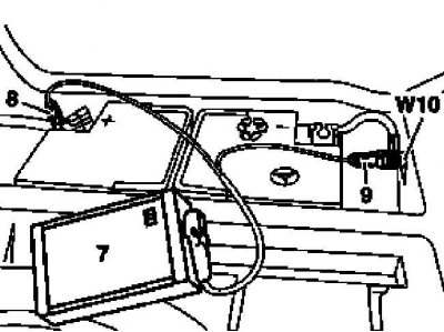
7 - Auxiliary battery
8 - Module positive wire terminal
9 - Terminal of the negative wire of the module
W10 - Battery Ground
2. Remove the panel of an internal upholstery of a door (see chapter Body).
3. Disconnect the wiring from the door control module (N69/1 or N69/2) (see Section Disconnecting and connecting wiring of mounting blocks and control modules).
4. Remove the fixing screws (IN) and remove the control module (N69/1 or N69/2).
5. Installation is carried out in the reverse order - the wiring of the modules, making sure that the wires do not cross, secure with new bandages (WITH).
6. Finally, read the DTCs and clear the OBD memory using the STAR DIAGNOSIS scanner (6511 1801 00) (see chapter Engine Electrical Systems).
Backdoor
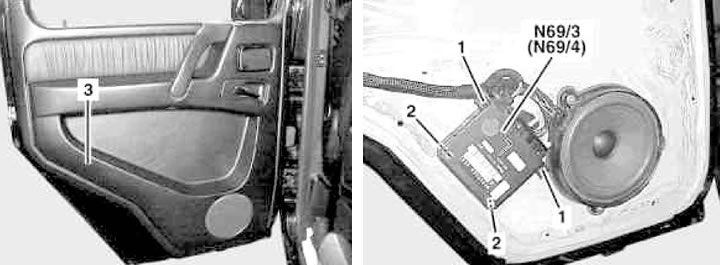
Rear door control module installation details (1 of 2)
1 - Clips; 2 - Latches; 3 - Upholstery panel; N69/3 - Left door control module; N69/4 - Right door control module
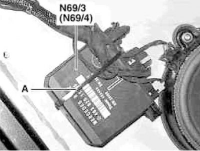
Rear door control module installation details (2 of 2)
A - binding
1. Turn on the auxiliary battery and connect it to the standard battery, then disconnect the negative wire from the latter.

7 - Auxiliary battery
8 - Module positive wire terminal
9 - Terminal of the negative wire of the module
W10 - Battery Ground
2. Remove the panel of an internal upholstery of a door (3) (see chapter Body).
3. Disconnect the wiring from the door control module (N69/3 or N69/4) (see Section Disconnecting and connecting wiring of mounting blocks and control modules).
4. Squeezing the latches (1), remove the control module (N69/3 or N69/4).
5. Installation is carried out in the reverse order - the wiring of the modules, making sure that the wires do not cross, secure with a new harness (A).
6. Finally, read the DTCs and clear the OBD memory using the STAR DIAGNOSIS scanner (6511 1801 00) (see chapter Engine Electrical Systems).
Control modules of the signal activation and perception system (SAM) /mounting blocks of fuses and relays
Front module
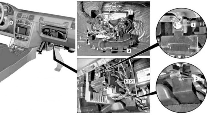
Installation Details of the Front SAM/Fuse and Relay Mounting Block
1, 2 - Nuts; 3, 4 - SAM wiring connector; N10/1 - Front SAM control module
1. On models of the corresponding configuration (code ET2) activate the service mode of the TELE AID emergency call system (see Section Activation / deactivation of the service mode of the TELE AID emergency call system).
2. Disconnect the negative cable from the battery.
3. Remove the main storage box (see chapter Body).
4. Remove the right lower instrument panel cover (see chapter Body).
5. Give fixing nuts (1 and 2) and remove the front SAM/mounting block (N10/1).
6. Having previously marked, disconnect the connectors (3 and 4) control module (N10/1) (see Section Disconnecting and connecting wiring of mounting blocks and control modules).
7. Installation is carried out in the reverse order - make sure that the electrical wiring is laid correctly and that its connectors are securely fixed (see Section Disconnecting and connecting wiring of mounting blocks and control modules).
8. Appropriate models (code ET2) deactivate the service mode of the TELE AID system (see Section Activation / deactivation of the service mode of the TELE AID emergency call system).
9. Finally, read the DTCs and clear the OBD memory using the STAR DIAGNOSIS scanner (6511 1801 00) (see chapter Engine Electrical Systems) and enter the required basic settings for the on-board equipment.
Rear module
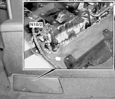
Rear SAM Installation Details/Fuse and Relay Mounting Block (N10/2)
1. On models of the corresponding configuration (code ET2) activate the service mode of the TELE AID emergency call system (see Section Activation / deactivation of the service mode of the TELE AID emergency call system).
2. Disconnect the negative cable from the battery.
3. Remove the center console (see chapter Body) and an air duct under it.
4. Loosen the mounting screws and remove the SAM module/mounting block (N10/2).
5. Installation is carried out in the reverse order - follow the correct wiring and the reliability of fixing its connectors (see Section Disconnecting and connecting wiring of mounting blocks and control modules).
6. Appropriate models (code ET2) deactivate the service mode of the TELE AID system (see Section Activation / deactivation of the service mode of the TELE AID emergency call system).
7. Finally, read the DTCs and clear the OBD memory using the STAR DIAGNOSIS scanner (6511 1801 00) (see chapter Engine Electrical Systems) and enter the required basic settings for the on-board equipment.
Electronic ignition switch control module (EIS/EZS)
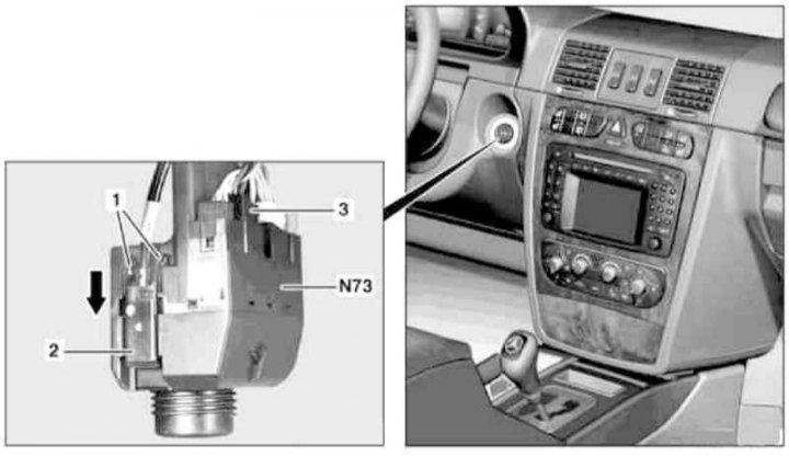
EIS/EZS Control Module Installation Details
1 - Clips; 2 - Drive cable of the ignition lock; 3 - Wiring connector; N73 - EIS/EZS control module
1. On models of the corresponding configuration (code ET2) activate the service mode of the TELE AID emergency call system (see Section Activation / deactivation of the service mode of the TELE AID emergency call system).
2. Turn on the auxiliary battery and connect it to the standard battery, then disconnect the negative cable from the latter.

7 - Auxiliary battery
8 - Module positive wire terminal
9 - Terminal of the negative wire of the module
W10 - Battery Ground
3. Remove the ignition key.
4. Remove the lower left section of the instrument panel trim (see chapter Body).
5. Squeeze the tabs (1) and disconnect from the EIS module (N73) drive cable (2), by pulling it in the direction indicated by the arrow.
6. Disconnect the connector (3) EIS module wiring (N73).
7. Installation is done in reverse order - the replacement EIS module must be programmed in accordance with the instructions included in the kit.
8. Finally, read the DTCs and clear the OBD memory using the STAR DIAGNOSIS scanner (6511 1801 00) (see chapter Engine Electrical Systems).
Telecom control module (ET7/EV7 codes)
Telecom Control Module Installation Details (ET7/EV7 codes)
1 - Module console; A - Connector for fiber optic cable connection; B - Connector; N112 - Control module
1. Remove the center console (see chapter Body).
2. Disconnect the connector (A) fiber optic cable connections on the control module (N112), - immediately close the waveguide connectors with protective plugs.
3. Squeeze the locking tabs and gently pull to disengage the connector (IN).
4. Turn out 2 fixing screws and having released one nut, remove the console (1) control module (N112) from the transmission line tunnel.
5. Turn out two fixing screws located from below and remove the control module (N112) from console panel (1).
6. Installation is carried out in the reverse order.
7. Finally, read the DTCs and clear the OBD memory using the STAR DIAGNOSIS scanner (6511 1801 00) (see chapter Engine Electrical Systems).
TELE AID emergency call system control module (code ET2)
Models 463.250/323/333
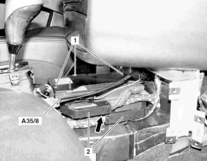
Installation details of the TELE AID emergency call system control module on models 463.250/323/333
1 - Screws; 2 - Wiring connectors; А35/8 - Control module; Arrow - Wiring connector
1. On models of the corresponding configuration (code ET2) activate the service mode of the TELE AID emergency call system (see Section Activation / deactivation of the service mode of the TELE AID emergency call system).
2. Disconnect the negative cable from the battery.
3. Remove the center console (see chapter Body).
4. Remove the AT control module (ECM/ETC) (see chapter automatic transmission).
5. Remove the three fixing screws (1), disconnect the two connectors (2), then disconnect the connector shown by the arrow and remove the control module (А35/8).
6. Replace the battery in the emergency call system.
7. Installation is carried out in the reverse order.
8. Appropriate models (code ET2) deactivate the service mode of the TELE AID system (see Section Activation / deactivation of the service mode of the TELE AID emergency call system).
9. Finally, read the DTCs and clear the OBD memory using the STAR DIAGNOSIS scanner (6511 1801 00) (see chapter Engine Electrical Systems) and enter the required basic settings for the on-board equipment.
Models 463.246/249
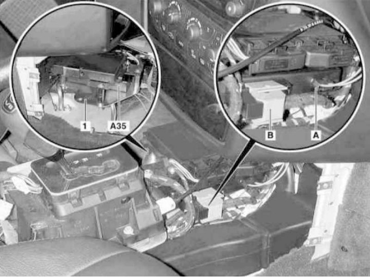
Installation details of the TELE AID emergency call system control module on models 463.246/249 (1 of 3)
1 - Control module cover; 3 - Fixing nut; А35/8 - Control module; A35/8j10 - Wiring connector; B - CAN data bus wiring connector; C - Antenna cable connector; Arrow - Clips
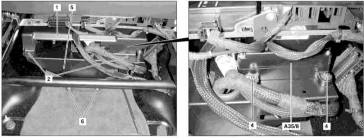
Installation details of the TELE AID emergency call system control module on models 463.246/249 (2 of 3)
4 - Fixing nut; 5 - Module console; 6 - Fixing nuts

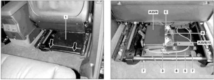
Installation details of the TELE AID emergency call system control module console on models 463.246/249 (3 of 3)
5 - Module console; 7 - Fixing nuts; 8 - CAN data bus wire; 9 - Porous insulating material
1. Raise the right front seat and slide it back as far as it will go.
2. Release the two latches (2) cover front fasteners (1) control module.
3. Move the raised seat all the way forward, release the two rear latches (arrows) and remove the cover (1).
4. Give two nuts (3) fixing the rear of the control module (А35/8).
5. Again take the raised seat to the rearmost position, give the two front nuts (4) and remove the module (А35/8).
6. Turn off the ignition, activate the auxiliary battery and connect it to the standard battery, then disconnect the negative wire from the latter.
7 - Auxiliary battery
8 - Module positive wire terminal
9 - Terminal of the negative wire of the module
W10 - Battery Ground
7. Remove the control module (А35/8) from the support bracket.
8. Unlock and disconnect the connector (A35/8j10).
9. Disconnect the CAN data bus fiber optic cable and immediately plug both halves of its connector (IN) special protective caps preventing light exposure.
10. Disconnect the connector (WITH) antenna cable.
11. Remove the TELE AID emergency call system control module (А35/8).
12. If necessary, release the front (6) and rear (7) nuts, separate from the console (5) the wire (8) CAN bus, free from foam insulation material (9) and disconnect the connectors, - take care of protecting the fiber optic waveguide with special caps and remove the console (5) module, passing the electrical wiring through the windows.
13. Installation is carried out in the reverse order.
14. Finally, read the DTCs and clear the OBD memory using the STAR DIAGNOSIS scanner (6511 1801 00) (see chapter Engine Electrical Systems) and enter the required basic settings for the on-board equipment.
Towing protection sensor control module
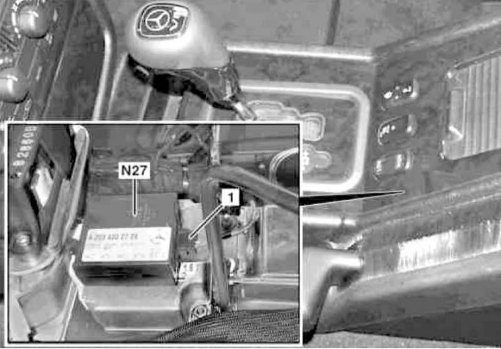
Control module installation details (N27) towing protection sensor
1. On models of the corresponding configuration (code ET2) activate the service mode of the TELE AID emergency call system (see Section Activation / deactivation of the service mode of the TELE AID emergency call system).
2. Disconnect the negative cable from the battery.
3. Remove the center console (see chapter Body).
4. Remove the rear SAM (N10/2), - see above.
5. Disconnect the wiring from the control module (N27) tow protection sensor.
6. Loosen the fasteners and remove the module (N27).
7. Installation is carried out in the reverse order - on models of the corresponding configuration (code ET2) deactivate the service mode of the TELE AID system (see Section Activation / deactivation of the service mode of the TELE AID emergency call system).
8. Finally, read the DTCs and clear the OBD memory using the STAR DIAGNOSIS scanner (6511 1801 00) (see chapter Engine Electrical Systems) and enter the required basic settings for the on-board equipment.
Ultrasonic Reverse Assist Control Module (BA) (code J44)
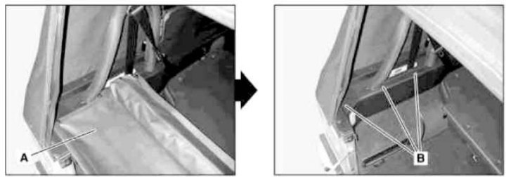
BA Control Module Installation Details (1 of 2)
A - Luggage cover with wind deflector; B - Wind deflector support bracket
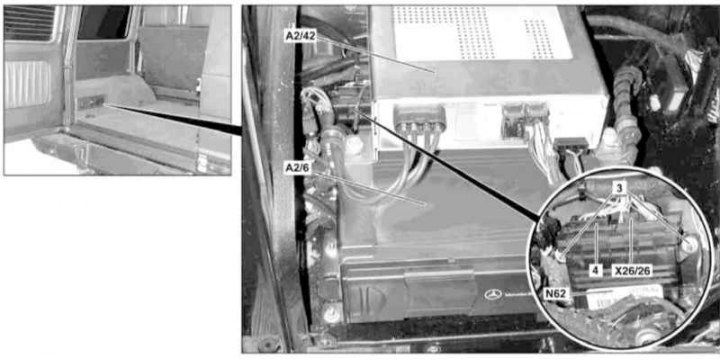
BA Control Module Installation Details (2 of 2)
3 - Nuts; 4 - Electrical wiring connector BA; A2 / 6 - CD changer; А2/42 - TV tuner; N62 - BA control module; X26/26 - Connector wiring BA
1. Turn off the ignition, activate the auxiliary battery and connect it to the standard battery, then disconnect the negative wire from the latter.

7 - Auxiliary battery
8 - Module positive wire terminal
9 - Terminal of the negative wire of the module
W10 - Battery Ground
2. Release six latches (three on each side), remove the wind deflector-equipped cover (A) baggage compartment.
3. Remove the support bracket (IN) wind deflector on the left side of the luggage compartment.
4. Appropriate models (code V53) remove the left storage box.
5. On eligible models, remove the TV tuner (A2/42), - code EM9 and CD changer (A2/6), - EP5 code (see Section Removing and installing CD changer/TV tuner).
6. Give fixing nuts (3), disconnect the connectors (Х26/26 and 4) and remove the BA control module (N62).
7. Installation is carried out in the reverse order.
8. Finally, read the DTCs and clear the OBD memory using the STAR DIAGNOSIS scanner (6511 1801 00) (see chapter Engine Electrical Systems).
Seat heating control module (code H11)
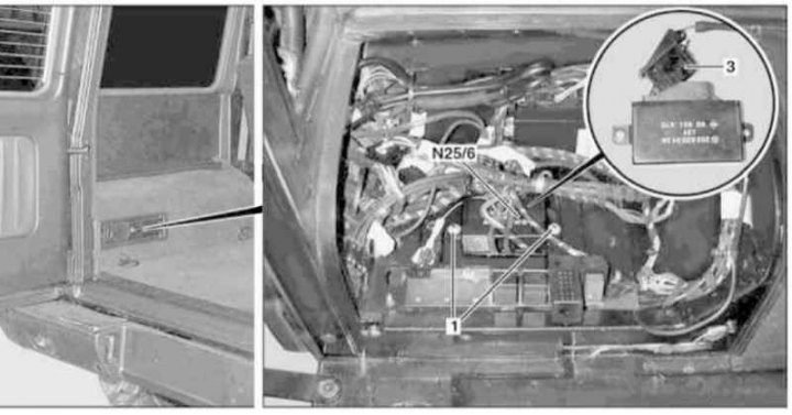
Seat heating control module installation details (code H11)
1 - Fixing nuts; 3 - Connector; N25/6 - Control module
1. On models of the corresponding configuration (code ET2) activate the service mode of the TELE AID emergency call system (see Section Activation / deactivation of the service mode of the TELE AID emergency call system).
2. Disconnect the negative cable from the battery.
3. Release six latches (three on each side), remove the wind deflector-equipped cover (A) baggage compartment.
4. Remove the support bracket (IN) wind deflector on the left side of the luggage compartment.
5. Appropriate models (code V53) remove the left storage box.
6. On eligible models, remove the TV tuner (A2/42), - code EM9 and CD changer (A2/6), - EP5 code (see Section Removing and installing CD changer/TV tuner).
7. Give fixing nuts (1), disconnect the connector (3) and remove the control module (N25/6).
8. Installation is carried out in the reverse order - on models of the corresponding configuration (code ET2) deactivate the service mode of the TELE AID system (see Section Activation / deactivation of the service mode of the TELE AID emergency call system).
9. Finally, read the DTCs and clear the OBD memory using the STAR DIAGNOSIS scanner (6511 1801 00) (see chapter Engine Electrical Systems) and enter the required basic settings for the on-board equipment.
Control module for the Linguatronic voice command system (codes EL1 to EL6)
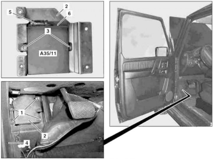
Installation details of the control module of the Linguatronic system
1, 3 - Nuts; 2 - Support bracket; 4 - Foot well finishing panel; 5 - Connector; 6 - D2V fiber optic cable connector; A35/11 - Linguatronic control module
1. Turn off the ignition, activate the auxiliary battery and connect it to the standard battery, then disconnect the negative wire from the latter.

7 - Auxiliary battery
8 - Module positive wire terminal
9 - Terminal of the negative wire of the module
W10 - Battery Ground
2. Peel back the carpet panel in the driver's footwell.
3. If necessary, lift the trim panel (4) and loosen the nuts (1).
4. Remove the Linguatronic control module (А35/11) complete with support bracket (2).
5. Release and disconnect connectors (5 and 6), - immediately plug the D2B fiber optic cable inputs with special plugs.
6. Give fixing nuts (3) and remove the control module (А35/11).
7. Installation is carried out in the reverse order.
8. Finally, read the DTCs and clear the OBD memory using the STAR DIAGNOSIS scanner (6511 1801 00) (see chapter Engine Electrical Systems).
Audio amplifier control module (code E66)
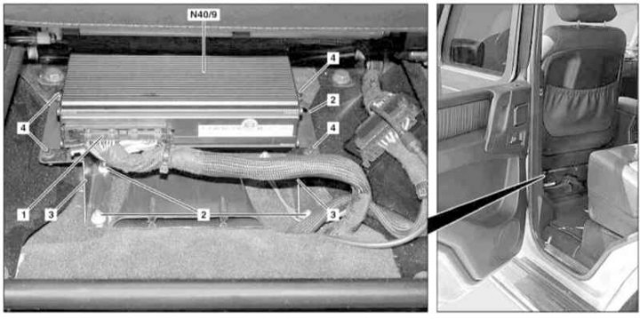
Audio amplifier control module installation details
1 - Wiring connector; 2 - Nuts; 3 - Console; 4 - Screws; N40/9 - Amplifier
1. Move the raised driver's seat forward until it stops.
2. Turn off the ignition, activate the auxiliary battery and connect it to the standard battery, then disconnect the negative wire from the latter.

7 - Auxiliary battery
8 - Module positive wire terminal
9 - Terminal of the negative wire of the module
W10 - Battery Ground
3. Disconnect the connector (1).
4. Give nuts (2) and remove the console (3) with an amplifier installed (N40/9).
5. Remove the fixing screws (4) and remove the amp (N40/9) from the console (3).
6. Installation is carried out in the reverse order.
7. Finally, read the DTCs and clear the OBD memory using the STAR DIAGNOSIS scanner (6511 1801 00) (see chapter Engine Electrical Systems).
SRS control module
Release models up to 11/30/01
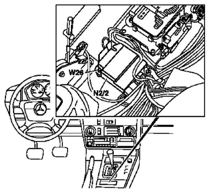
SRS Control Module Installation Details on 11/30/01 Models
N2/2 - Control module
W26 - Module ground
1. Disconnect the negative cable from the battery.
2. Remove the center console (see chapter Body).
3. Disconnect from control module (N2/2) electrical wiring - try to remember the ground connection diagram (W26)
4. Loosen the fixing screws and remove the module (N2/2).
5. Installation is carried out in the reverse order - the marking in the form of an arrow on the casing of the installed module must point forward in the direction of travel.
6. Finally, enter the SRS program data.
Release models from 01.12.01
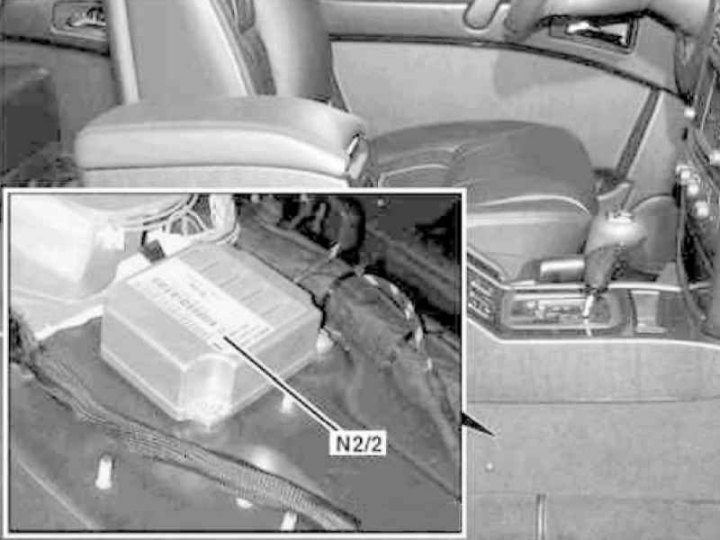
SRS control module installation details (N2/2) on production models from 01.12.01
1. Remove the towing protection control module (see above).
2. Disconnect the electrical wiring, release the fasteners and remove the SRS control module (N2/2), - try to remember the ground connection diagram (W26).
3. Installation is carried out in the reverse order.
4. Finally, read the DTCs and clear the OBD memory using the STAR DIAGNOSIS scanner (6511 1801 00) (see chapter Engine Electrical Systems).