
Parktronic sensors
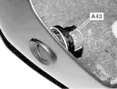
PTS sensors (A43) fixed in the rear bumper panel of the car
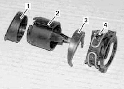
Scheme of organization of fastening of the PTS sensor
1 - Cover; 2 - Holder; 3 - Nozzle; 4 - Bracket
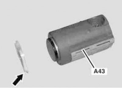
Fixing the sensor (A43) in the bracket is carried out by means of a retaining ring (arrow)
1. Remove the license plate light.
2. Release the retaining ring on the holder (2) and release the sensor from the bracket (4).
3. Remove retaining ring (arrow).
4. Carefully separate the electrical wiring.
5. Installation is carried out in the reverse order, if necessary, paint the sensors in body color.
Note. Sensors with a scratched outer surface must be replaced.
Towing protection sensor
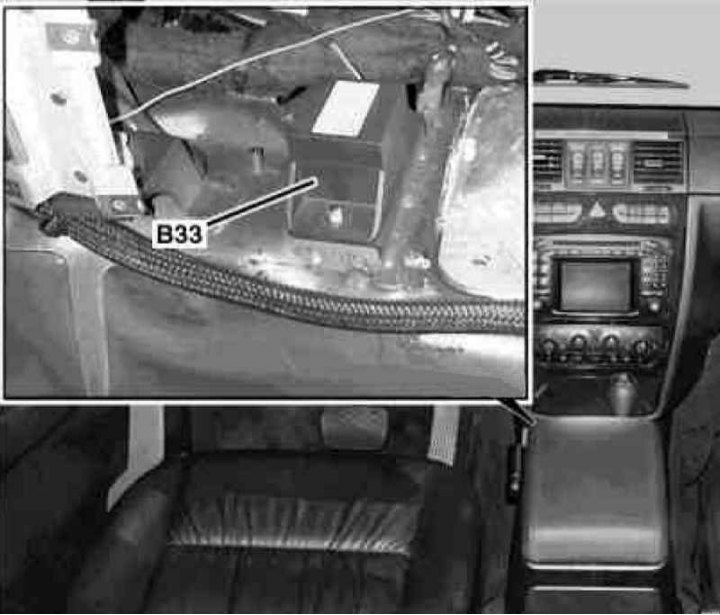
Installation details of the towing protection sensor (B33)
1. On models of the corresponding configuration (code ET2) activate the service mode of the TELE AID emergency call system (see Section Activation / deactivation of the service mode of the TELE AID emergency call system).
2. Turn on the auxiliary battery and connect it to the standard battery, then disconnect the negative cable from the latter.
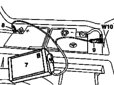
7 - Auxiliary battery
8 - Module positive wire terminal
9 - Terminal of the negative wire of the module
W10 - Battery Ground
3. Remove the center console (see chapter Body).
4. Remove the AT control module (TCM/ETC) (see chapter automatic transmission).
5. On models 463.246/249, remove the TELE AID emergency call system control module (see Section Removing and installing control modules).
6. Remove the control module support bracket.
7. Disconnect the wiring harness from the tilt-sensing towing protection sensor (B33).
8. Unscrew from the housing and remove the sensor (B33).
9. Installation is carried out in the reverse order, on models of the corresponding configuration (code ET2) deactivate the service mode of the TELE AID system (see Section Activation / deactivation of the service mode of the TELE AID emergency call system).
10. Finally, read the DTCs and clear the OBD memory using the STAR DIAGNOSIS scanner (6511 1801 00) (see chapter Engine Electrical Systems) and follow the basic programming procedures.
Daylight sensor
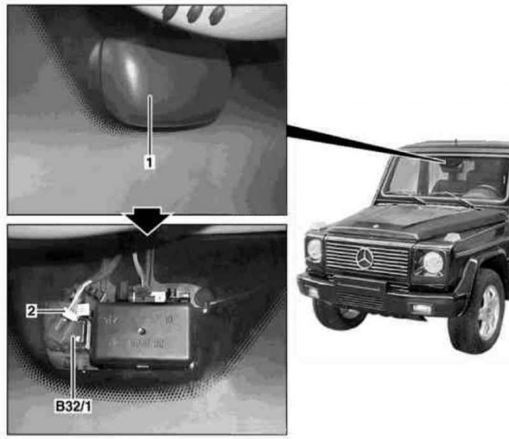
Daylight Sensor Installation Details (B32/1)
1 - Cover; 2 - Connector
1. Remove interior rearview mirror (see chapter Body).
2. Remove the cover (1).
3. Disconnect the connector (2), release the clips and remove the daylight sensor (B32/1), - the sensor lens is glued to the windshield and cannot be replaced.
4. Installation is carried out in the reverse order.
Rain sensor
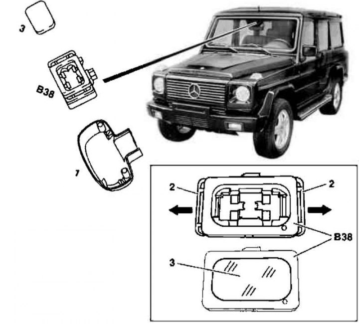
Rain sensor installation details (B38)
1 - Cover; 2 - Clamps; 3 - Lens
1. Remove interior rearview mirror (see chapter Body).
2. Remove the cover (1).
3. Release the latches (2) left and right and remove the rain sensor (B38), - the sensor lens is glued to the windshield and cannot be replaced.
4. Disunite a socket of electroconducting of the gauge.
5. Installation is carried out in the reverse order.