
Power back and headrest
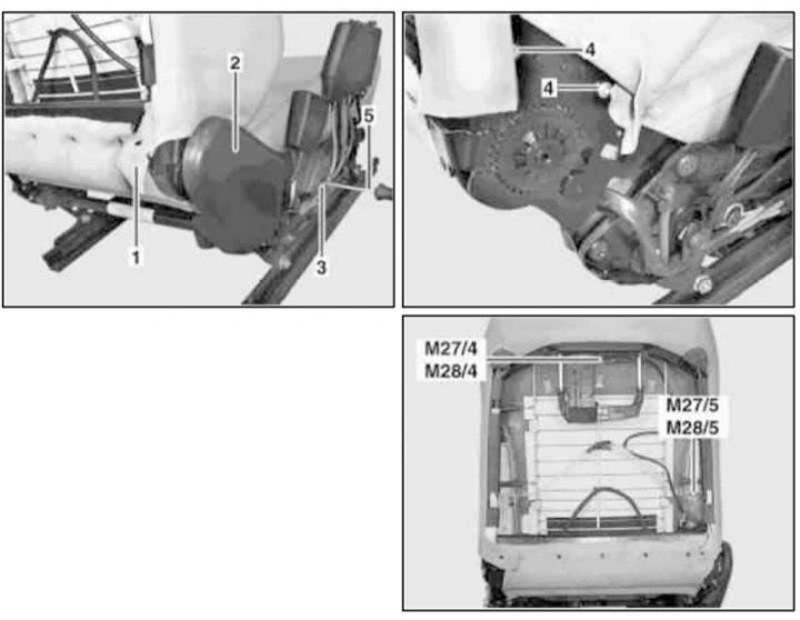
Installation details of electric motors for adjusting the backrest and headrest of the front seat
1 - Cover; 2 - Overlay; 3, 4 - Screws; 5 - Screwdriver; M27 / 4 - Drive motor for adjusting the headrest of the left seat; M28 / 4 - Drive motor for adjusting the headrest of the right seat; M27 / 5 - Drive motor for adjusting the backrest of the left seat; M27 / 6 - Drive motor for adjusting the backrest of the right seat
1. Remove the front seat assembly (see chapter Body).
2. Turn out fixing screws and remove a back upholstery of a back.
3. Remove the head restraint.
4. Disconnect the electrical wiring from the headrest adjustment motor (M27/4 or M28/4).
5. Sliding to the right, remove the electric motor through the bottom of the backrest (M27/4 or M28/4).
6. Remove the fixing screws (3) and remove the trim (2).
7. On the right side, detach the cover (1) backs.
8. Remove the screws on the right (4), remove the backrest adjustment motor (M27/5 or M28/5) and disconnect the wiring from it.
9. Installation is carried out in the reverse order.
Electric cushion
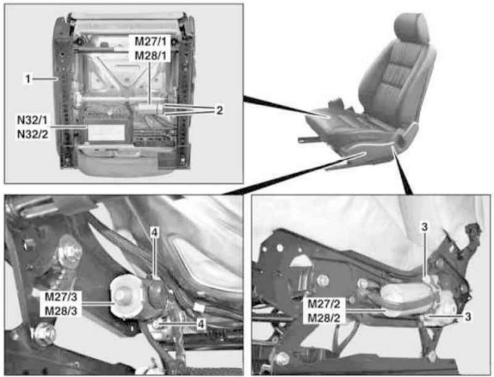
Details of installation of electric motors of a drive of adjustment of a pillow of a forward seat
1 - Overlay; 2, 3, 4 - Screws; M27 / 1 - Drive motor for adjusting the left seat cushion in the longitudinal direction; M28 / 1 - Drive motor for adjusting the right seat cushion in the longitudinal direction; M27 / 2 - Drive motor for adjusting the rear edge of the left seat cushion in the vertical direction; M28 / 2 - Drive motor for adjusting the rear edge of the right seat cushion in the vertical direction; M27 / 3 - Motor for adjusting the front edge of the left seat cushion in the vertical direction; M28 / 3 - Motor drive for adjusting the front edge of the right seat cushion in the vertical direction; N32/1 - Driver's seat adjustment control unit with memory (and steering column); N32/2 - Memory-equipped passenger seat adjustment control unit
1. Remove the front seat assembly (see chapter Body).
2. Separate the memory-equipped seat adjustment control unit (N32/1 or N32/2) and disconnect the electrical wiring from it, - prepare replaceable bandages.
3. Remove the screws (2) and remove the drive motor (M27/1 or M28/1).
4. Remove the trim (1), remove the screws (3) and remove the motor (M27/2 or M28/2).
5. For removing motors (M27/3 or M28/3) remove the screws (4).
6. Installation is carried out in the reverse order.